A Method for Determining Local Surface Normal Vectors Based on Dual Infrared Sensors

A determination method and sensor technology, applied in instruments, measuring devices, optical devices, etc., can solve problems such as the inability of measuring technology to be realized, and achieve the effect of overcoming errors and inefficiencies, avoiding measuring equipment, and processing efficiently.

Active Publication Date: 2019-03-12
宁波智能装备研究院有限公司
View PDF13 Cites 0 Cited by
  • Summary
  • Abstract
  • Description
  • Claims
  • Application Information

AI Technical Summary

Problems solved by technology

[0007] The invention provides a method for determining the normal vector of a local surface based on dual infrared sensors, aiming to solve the problem that the existing measurement technology cannot realize, so as to improve the efficiency of finding the normal vector of the local surface and the processing quality of the workpiece

Method used


Image

  • A Method for Determining Local Surface Normal Vectors Based on Dual Infrared Sensors
  • A Method for Determining Local Surface Normal Vectors Based on Dual Infrared Sensors
  • A Method for Determining Local Surface Normal Vectors Based on Dual Infrared Sensors

Examples


specific Embodiment approach 1

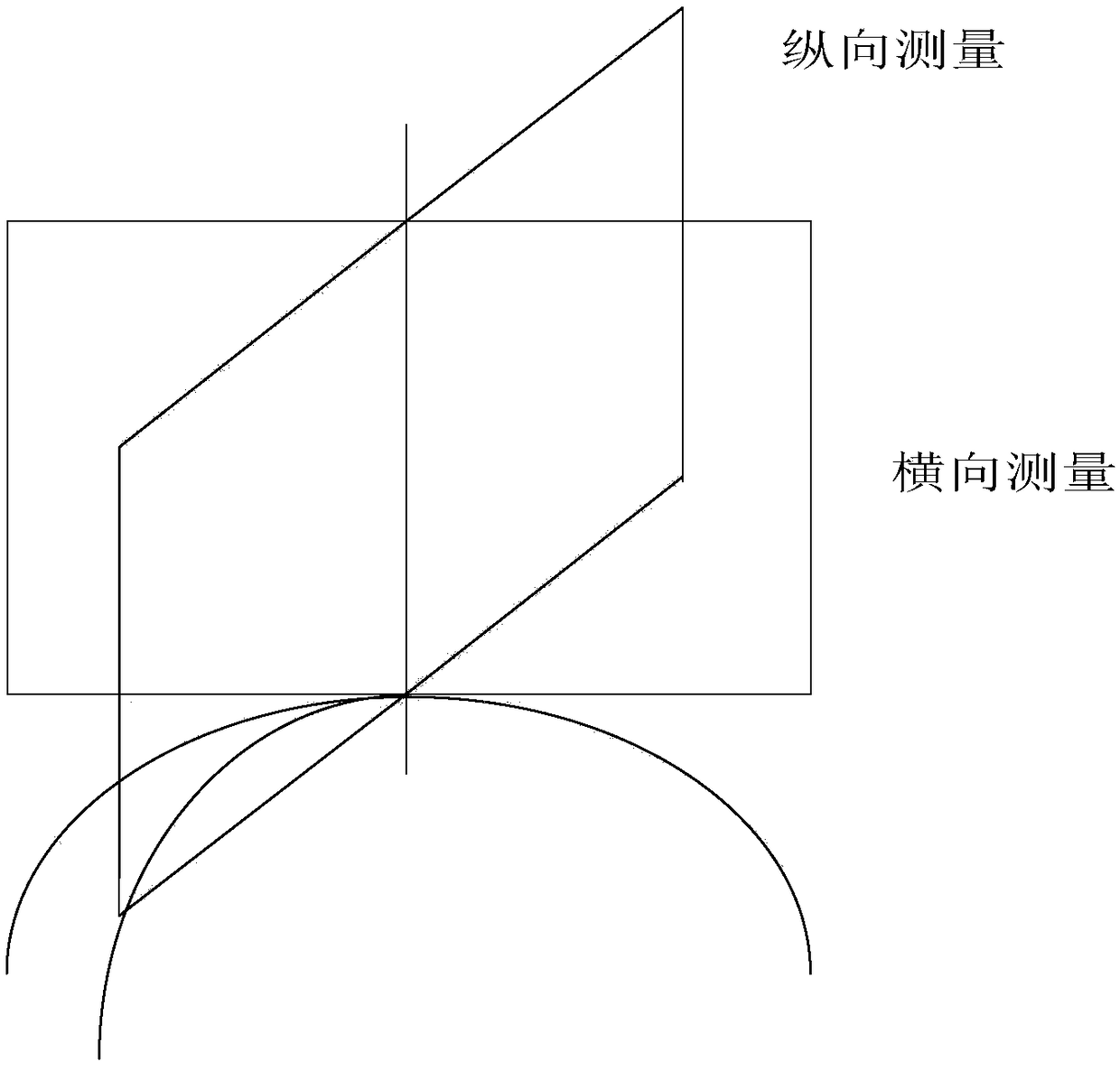
[0039] Specific implementation mode one: combine figure 1 , figure 2 , image 3 , Figure 4 and Figure 5 To illustrate this embodiment, a method for determining local surface normal vectors based on dual infrared sensors in this embodiment includes two parts: lateral measurement and longitudinal measurement;

[0040] 1. The implementation steps of the longitudinal measurement method are as follows:

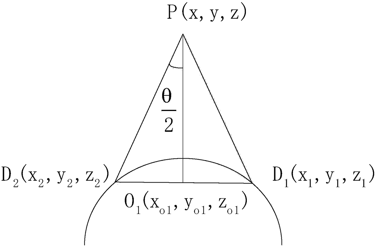
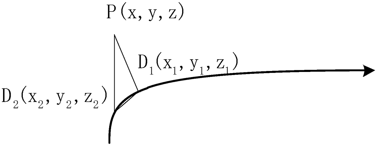
[0041] Step 11: After the robot nozzle moves to the position of the curved surface of the workpiece to be sprayed, obtain the coordinates of the robot nozzle in the earth coordinate system and set it as P(x,y,z), (x,y,z conform to the right-hand rule) ;

[0042] Step 1 and 2: According to the angle θ between the two infrared ranging sensors set on the edge of the robot nozzle, and the distance d between the two infrared sensors and the curved surface of the workpiece to be sprayed measured by the infrared sensor 1 、d 2 , the two points D on the surface of the workpiece to...

specific Embodiment approach 2

[0060] Specific implementation mode two: the difference between this implementation mode and specific implementation mode one is: in the step one or two, D 1 (x 1 ,y 1 ,z 1 ), D 2 (x 2 ,y 2 ,z 2 ) The specific formula is:

[0061]

[0062]

[0063] Other steps and parameters are the same as those in Embodiment 1.

specific Embodiment approach 3

[0064] Embodiment 3: The difference between this embodiment and Embodiment 1 or 2 is: the intersection point O in the step 1 and 31 (x o1 ,y o1 ,z o1 ) The specific formula is:

[0065]

[0066] Other steps and parameters are the same as those in Embodiment 1 or Embodiment 2.


PUM


Abstract

The invention relates to a local curved surface normal vector determining method based on double infrared sensors. The objective of the invention lies in solving a problem that a conventional measurement method cannot achieve the determining of a local curved surface normal vector. The method comprises two parts: lateral measurement and longitudinal measurement. The longitudinal measurement comprises the following steps: obtaining the coordinates of a robot nozzle in the geodetic coordinate system, and determining that the robot nozzle is located in a lateral plane which is perpendicular to a to-be-sprayed workpiece surface; the lateral measurement comprises the following steps: obtaining the coordinates P(x, y, z) of the robot nozzle in the geodetic coordinate system, recording the sampling points where the robot nozzle passes by in a moving process, and determining that the robot nozzle is in a longitudinal plane which is perpendicular to the to-be-sprayed workpiece surface; repeatedly carrying out the lateral measurement and longitudinal measurement, enabling the lateral plane to be intersected with the longitudinal plane, and determining the normal vector of the to-be-sprayed workpiece surface. The method is used in the spraying field.

Description

technical field [0001] The invention relates to a method for determining local surface normal vectors based on double infrared sensors. Background technique [0002] In the spraying technology, keeping the nozzle vertical to the surface of the workpiece is a very important link in the whole process. Keeping the nozzle perpendicular to the surface of the workpiece at all times can ensure the thickness of the spray paint, the spray effect, and the degree of gloss. The effect of the workpiece after processing. The traditional measurement method is to determine the normal direction by offline measurement, that is, in the process of processing parts, in order to keep the processing tool perpendicular to the surface, it is necessary to stop the equipment and manually teach. It can only be judged by the naked eye whether the processing tool coincides with the normal direction of the surface. [0003] With the popularization of automation technologies such as spraying technology, ...

Claims


Application Information

Patent Timeline
Patent Type & Authority Patents(China)
IPC IPC(8): G01B11/00
CPCG01B11/002
Inventor 李湛董文博林伟阳于兴虎
Owner 宁波智能装备研究院有限公司
Why Eureka
Try Eureka