Detection method and device of surface shape of optical aspheric surface
A detection method and detection device technology, applied in the direction of using optical devices, measuring devices, instruments, etc., can solve the problems of complex manufacturing and poor versatility, and achieve the effect of simple structure, strong versatility, and high measurement accuracy
- Summary
- Abstract
- Description
- Claims
- Application Information
AI Technical Summary
Problems solved by technology
Method used
Image

Examples
Embodiment Construction
[0028] In order to make the object, technical solution and advantages of the present invention clearer, the present invention will be further described in detail below in conjunction with the accompanying drawings and embodiments. It should be understood that the specific embodiments described here are only used to explain the present invention, not to limit the present invention.
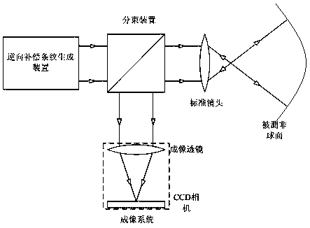
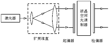
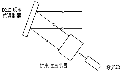
[0029] An embodiment of the present invention provides a method for detecting the shape of an optical aspheric surface. The method includes: after the reverse compensation fringes are irradiated from the projection direction onto the measured aspheric surface, the measured aspheric surface is reflected and imaged by the imaging system to obtain the The modulation fringes of the aspheric surface shape information, the surface shape deviation of the aspheric surface is obtained according to the modulation fringes, and the processing condition of the measured aspheric surface is determined according to...
PUM
 Abstract
Description
Claims
Application Information
PatSnap Eureka turns technology decisions into work you can execute. Powered by our Innovation Knowledge Graph, it runs expert workflows across engineering, life sciences, materials and intellectual property. Get your review-ready output in minutes.


