
A laser detection method for cracks in fan blades during operation

A fan blade and laser detection technology, applied to measuring devices, measuring ultrasonic/sonic/infrasonic waves, instruments, etc., can solve problems such as large noise influence, poor signal-to-noise ratio of fault signals, and unobvious vibration characteristics, so as to improve maintenance efficiency , The measuring instrument is simple and the effect of saving man-hours

Active Publication Date: 2019-09-13
东营市广利临港产业园有限公司 +1
View PDF3 Cites 0 Cited by
  • Summary
  • Abstract
  • Description
  • Claims
  • Application Information

AI Technical Summary

Problems solved by technology

[0003] At present, the fault diagnosis of fan blade cracks is mostly based on the test and analysis of vibration signals, but the sensor must be attached to the surface of the test component to obtain the vibration signal, and the sensor is not easy to install in the working environment of the fan blade
In addition, when the fan blade has cracks, the vibration characteristics are not obvious, and it is greatly affected by noise, and the signal-to-noise ratio of the fault signal is poor, which limits the application of fan blade fault diagnosis technology based on vibration signals.

Method used


Image

  • A laser detection method for cracks in fan blades during operation
  • A laser detection method for cracks in fan blades during operation
  • A laser detection method for cracks in fan blades during operation

Examples


Embodiment Construction

[0032] In order to enable those skilled in the art to better understand the present invention, the technical solution of the present invention will be further described below in conjunction with the accompanying drawings and embodiments.

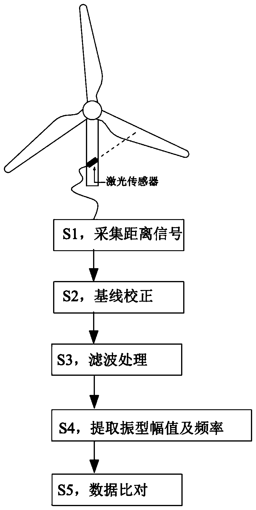
[0033] Such as figure 1 As shown, a laser detection method for cracks in fan blades in operation includes the following steps,

[0034] S1, collect the distance signal, install a displacement sensor on the fan to collect the distance signal of the blade;

[0035] S2, baseline correction, performing baseline correction on the collected distance signal;

[0036] S3, filtering processing, performing filtering processing on the baseline-corrected signal;

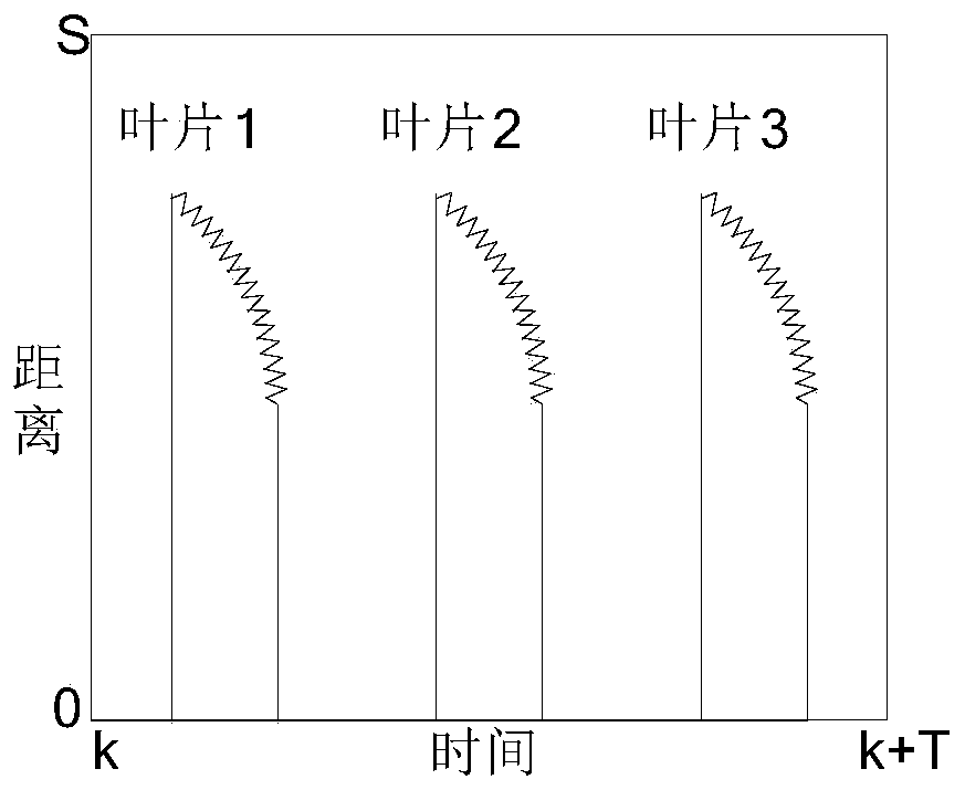
[0037] S4, extracting the vibration amplitude and frequency, independently extracting the vibration amplitude and frequency of each blade;

[0038] S5, data comparison, comparing the vibration mode and amplitude of each blade with the historical data of the blade and the current data of oth...


PUM


Abstract

The invention discloses a laser detection method for cracks of a fan blade in operation, relates to the technology of mechanical equipment fault diagnosis and is used for solving the problem that fault diagnosis of cracks of a fan blade is almost based on test and analysis of vibrating signals, but a sensor must be attached to the surface of a tested part for acquisition of the vibrating signals and the sensor is hard mounted. The method comprises the following steps: S1, collecting a distance signal, namely mounting a displacement sensor on the fan to collect the distance signal of the blade; S2, baseline correction, namely performing baseline correction on the collected distance signal; S3, filter processing, namely performing filter processing on the signal subjected to baseline correction; S4, extracting a mode of vibration, amplitude and frequency, namely independently extracting the mode of vibration and the amplitude and frequency of each blade; and S5, data comparison, namely comparing the model of vibration and amplitude of each blade with historical data of the blade and current data of other blades to judge the blade with cracks. The laser detection method based on non-contact measurement increases the fault detection rate.

Description

technical field [0001] The invention relates to a fault diagnosis technology of mechanical equipment, in particular to a laser detection method for cracks in fan blades during operation. Background technique [0002] Wind turbines are installed in harsh environments in the wild and are often left unattended, so monitoring their operating status is particularly important. The blade is an important part of the fan rotor system. Blade crack failure is a common failure of rotating machinery. Once it occurs, if it is not dealt with in time, it will eventually cause the blade to break, which will pose a serious threat to the safe operation of the entire unit, and even lead to major accidents. , causing huge economic losses. Timely and accurate judgment of the crack failure of the fan blade is the key to ensure the healthy service of the fan unit. [0003] At present, the fault diagnosis of fan blade cracks is mostly based on the test and analysis of vibration signals, but the se...

Claims


Application Information

Patent Timeline
Patent Type & Authority Patents(China)
IPC IPC(8): G01N29/04G01H9/00
Inventor 李川白云陈志强喻其炳陈旭东姚行艳成志伟李雪娇王晓丹
Owner 东营市广利临港产业园有限公司
Learn More