Distributed farmland irrigation facility expense control system

A distributed, agricultural drainage technology, applied in the field of agricultural drainage, can solve problems such as non-compliance with the development trend, and achieve the effect of being beneficial to system maintenance, facilitating maintenance and replacement, and reducing economic disputes.

Active Publication Date: 2017-08-18
CHINA ELECTRIC POWER RES INST +4
View PDF6 Cites 1 Cited by
  • Summary
  • Abstract
  • Description
  • Claims
  • Application Information

AI Technical Summary

Problems solved by technology

[0004] The purpose of the present invention is to provide a distributed agricultural row fee control sy

Method used


Image

  • Distributed farmland irrigation facility expense control system
  • Distributed farmland irrigation facility expense control system
  • Distributed farmland irrigation facility expense control system

Examples


Embodiment 1

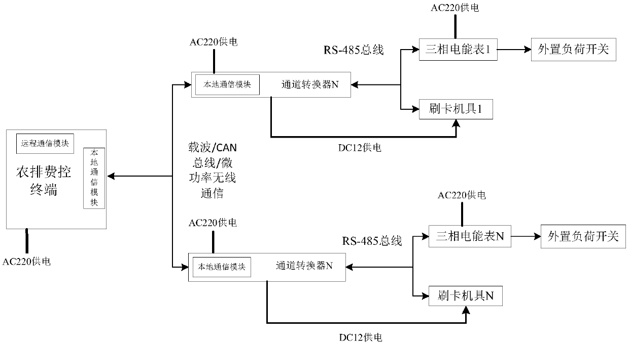
[0023] Such as figure 1 As shown, the distributed agricultural row fee control system provided in this embodiment includes an agricultural row fee control terminal and at least two distributed devices. The agricultural row fee control terminal is connected to each distributed device in communication. meters and load switches, etc. Since the motor in the water pump used in agricultural drainage is usually a three-phase AC motor, the electric energy meter is a three-phase electric energy meter. For a well, the three-phase alternating current is connected to the water pump in the well through the power supply line, and a three-phase electric energy meter and a load switch are arranged in series on the power supply line (because the load switch is external, the load switch is called External load switch), the three-phase electric energy meter is used to detect the electric quantity information of the water pump. Wherein, the distributed device is just a general term defined for ...

Embodiment 2

[0046] In the distributed agricultural row fee control system in this embodiment, there is no need to specially set up an external load switch, and the original load switch in the line can be used. Then, in the distributed agricultural row fee control system in this embodiment, there is no Including the load switch, while the other components in the system are still the same as in the above-mentioned embodiment 1, since the other components in the system have been described in detail in the above-mentioned embodiment 1, no specific description will be given here .


PUM


Abstract

The invention relates to a distributed farmland irrigation facility expense control system. A farmland irrigation facility expense control terminal is in communication connection with distributed devices comprising credit card machines, electric energy meters and external load switches, wherein the electric energy meters are used for acquiring electric energy information of corresponding water pumps, the external load switches are serially arranged on water supply lines of the corresponding water pumps, the farmland irrigation facility expense control terminal is connected with the credit card machines and the electric energy meters in the distributed devices, and the electric energy meters are connected with the corresponding external load switches by control. The system adopts a modular structure, and each portion is an independent device. Compared with a traditional electric meter integrating all functions, the system has the advantage that the influence of other functions on metering function accuracy is reduced. The farmland irrigation facility expense control system is more reasonable in functional framework, data are acquired in a distributed manner and processed and uploaded in a centralized manner, the risk of electric shock of users is greatly reduced by strong and weak electric isolation, and the farmland irrigation facility expense control terminal is a state grid I-type collector function expansion board and can be in seamless butt joint with a current electricity colleting system main station.

Description

technical field [0001] The invention relates to a distributed agricultural platoon fee control system, which belongs to the technical field of agricultural platooning. Background technique [0002] As one of the most effective drought-resistant and moisture-resisting measures in the main grain-producing areas of central, western and northern my country, farmland machine-well irrigation has been issued by the state for many years to support and guarantee the construction of agricultural drainage projects. Farm row is a kind of farmland irrigation facility, which is generally composed of wells, water pumps, power supply lines, transformers and other facilities. The current agricultural discharge fee control system is mainly completed by multi-functional three-phase meters, implementing one meter and one well, and a single electric meter realizes functions such as metering, billing, and settlement. Acquisition requires manual on-the-spot copying of tables one by one, which inc...

Claims


Application Information

Patent Timeline
IPC IPC(8): G07F15/00G06Q50/06G06Q50/02G08C19/00
CPCG06Q50/02G06Q50/06G07F15/003G08C19/00
Inventor 秦楠华隽孔令达徐景涛刘利兵冯海舟彭楚宁王雍
Owner CHINA ELECTRIC POWER RES INST
Why Eureka
Try Eureka