
Current-variable, self-excitation and self-charging converter of switch reluctance generator

A switched reluctance, self-charging technology, applied in the direction of controlling generators, generators, and electrical components through magnetic field changes, can solve the problem of increasing the torque ripple of switched reluctance generators, uncontrolled winding currents, and increasing Labor costs and other issues, to achieve the effect of improving adaptability, reliable charging, and reducing consumption

Active Publication Date: 2017-08-18
CHINA JILIANG UNIV
View PDF6 Cites 8 Cited by
  • Summary
  • Abstract
  • Description
  • Claims
  • Application Information

AI Technical Summary

Problems solved by technology

[0005] In many fields, especially in the field of wind power applications, the maximum power output, that is, MPPT control, is a research hotspot. That is to say, it is very important to increase the power generation capacity of the generator as much as possible. It is very important to control the power output, but the uncontrolled winding current in the power generation stage has always been a heart problem for researchers in the industry;
[0006] From the perspective of the source of excitation power in the excitation stage of the switched reluctance generator, there are self-excited and separate excited types. The traditional self-excited type has large current fluctuations, which increases the torque ripple of the switched reluctance generator, which is very unfavorable. The current of the excited type is stable, but the traditional separately excited type needs to replace the battery frequently, which increases the labor cost. If the advantage of the stable power supply of the battery is used, and it can be automatically charged, it is a meaningful design.

Method used


Image

  • Current-variable, self-excitation and self-charging converter of switch reluctance generator

Examples


Embodiment Construction

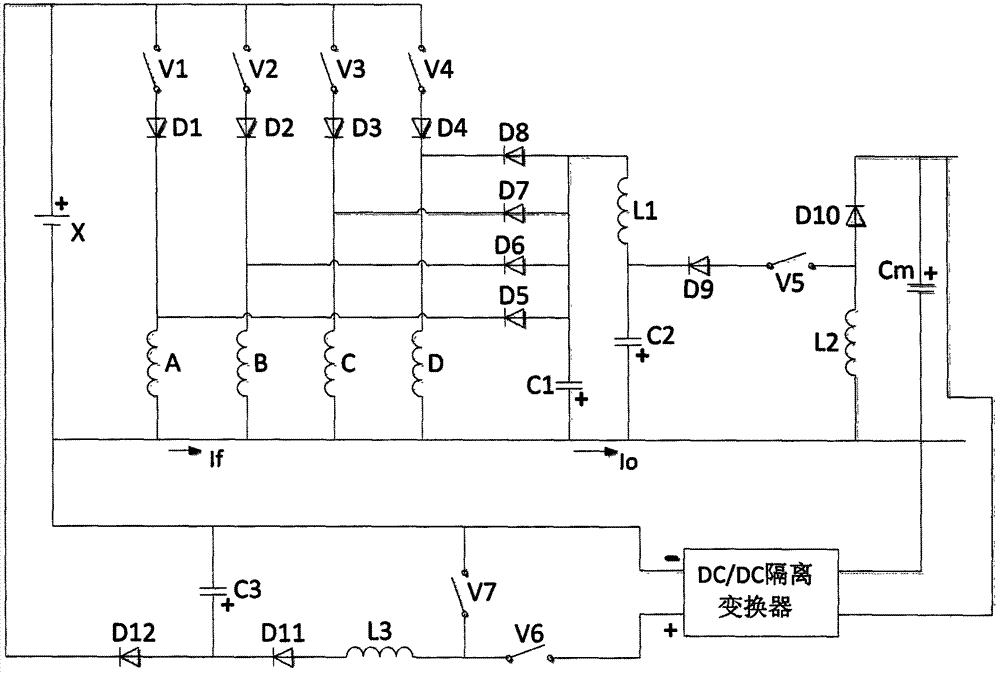
[0020] Variable current self-excited self-charging switched reluctance generator converter, as attached figure 1 As shown, the storage battery X, the first switching tube V1, the second switching tube V2, the third switching tube V3, the fourth switching tube V4, the fifth switching tube V5, the sixth switching tube V6, the seventh switching tube V7, the A diode D1, a second diode D2, a third diode D3, a fourth diode D4, a fifth diode D5, a sixth diode D6, a seventh diode D7, an eighth diode Diode D8, ninth diode D9, tenth diode D10, eleventh diode D11, twelfth diode D12, first phase winding A, second phase winding B, third phase Composition of winding C, fourth phase winding D, first capacitor C1, second capacitor C2, third capacitor C3, first inductance L1, second inductance L2, third inductance L3, bus capacitor Cm, DC / DC isolation converter , the positive pole of the battery X is connected to the anode of the first switching tube V1, the anode of the second switching tube...


PUM


Abstract

A current-variable, self-excitation and self-charging converter of a switch reluctance generator comprises a storage battery, eight switch tubes, twelve diodes, four phase windings, four capacitors, three inductors and a DC / DC isolation converter, wherein each phase winding is corresponding to each switch tube to achieve closed excitation and power generation disconnection, a power generation current is adjusted by adjusting a fifth switch tube, and the storage battery is charged by adjusting a sixth switch tube and a seventh switch tube. The converter is simple in structure, the power generation current is controllable, the excitation storage battery can be automatically charged, and the converter can be applied to the fields of wind power generation, an automobile charger and the like.

Description

technical field [0001] The invention relates to the field of switched reluctance motors, in particular to a self-excited switched reluctance generator converter capable of changing generating current and capable of self-charging and excitation and a switch control method thereof. Background technique [0002] The use of switched reluctance motors as generators is a new practical exploration in the current industry, especially in the fields of wind power generation and car chargers. [0003] The converter of the switched reluctance generator is a key component during its operation, and also a core component to achieve high efficiency and high reliability operation. [0004] Since most of the fields where switched reluctance generators are applied are focused on their simple structure, firmness and low cost, the simple structure of the converter part is very important; [0005] In many fields, especially in the field of wind power applications, the maximum power output, that ...

Claims


Application Information

Patent Timeline
Patent Type & Authority Applications(China)
IPC IPC(8): H02P9/00H02P9/38
CPCH02P9/00H02P9/38
Inventor 孙冠群
Owner CHINA JILIANG UNIV
Learn More