Bioerodible polymeric stent scaffolding pattern

A polymer and biological technology, applied in the field of polymer stents, can solve problems such as complicated processing operations

Inactive Publication Date: 2017-08-18
BOSTON SCI SCIMED INC
View PDF6 Cites 0 Cited by
  • Summary
  • Abstract
  • Description
  • Claims
  • Application Information

AI Technical Summary

Problems solved by technology

The anisotropy and rate-dependent inelastic properties of polymeric materials (i.e., the strength/stiffness of the material varies according to the ra

Method used


Image

  • Bioerodible polymeric stent scaffolding pattern
  • Bioerodible polymeric stent scaffolding pattern
  • Bioerodible polymeric stent scaffolding pattern

Examples


Embodiment Construction

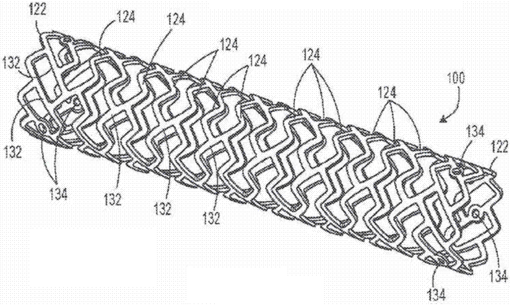
[0024] figure 1 Stent 100 is depicted, an example of a stent provided by the present invention. The bracket 100 is cylindrical. Stent 100 includes a plurality of straps having end straps 122 and a plurality of inner straps 124 . Each end band 122 and each inner band 124 includes nine peaks. Each inner strip 124 is connected to two adjacent strips by a plurality of connectors 132 . Each connector 132 extends peak-to-peak between adjacent strips. Each end band 122 is connected to an adjacent inner band 124 by nine connectors 132 . The individual inner bands 124 are connected by three equally spaced connectors 132 . Option connectors 132 extending from each end band include radiopaque markers 134 . The stent 100 can be a self-expanding stent or a balloon-expandable stent, or a part of a covered stent.

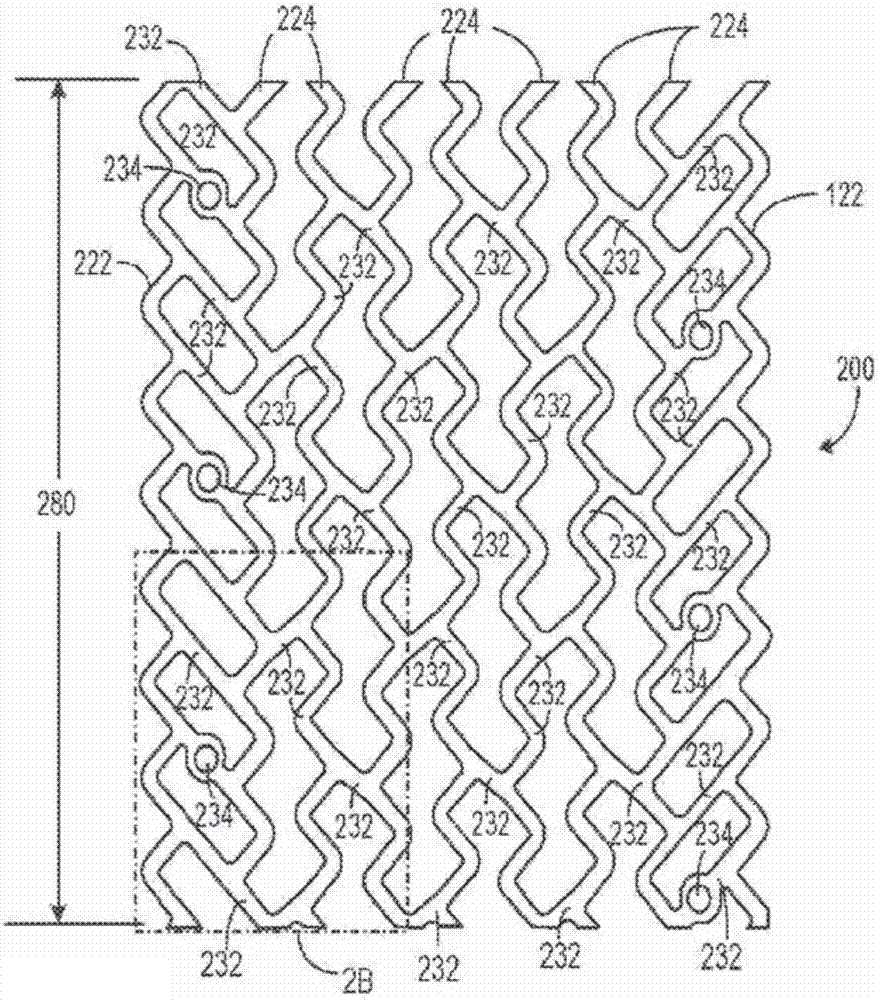
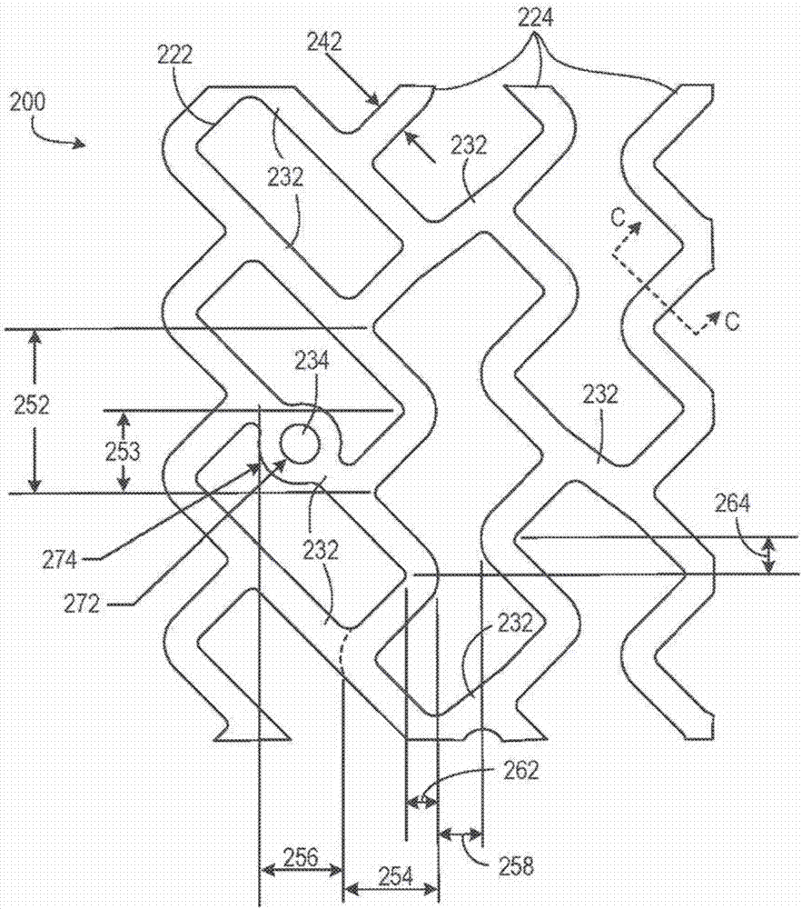
[0025] Figure 2A Depicted is a plan view of a stent outer diameter surface having a skeleton pattern provided by the present invention. Figure 2B show Figure 2A Deta...


PUM

PropertyMeasurementUnit
Wall thicknessaaaaaaaaaa
Curl diameteraaaaaaaaaa

Abstract

A stent includes a tubular network of struts cut from a bioerodible polymer tube. The tubular network includes a plurality of bands and a plurality of connectors. Each band includes at least nine peaks. Each band being connected to one or more adjacent bands by at least two connectors.

Description

[0001] Cross References to Related Applications [0002] This application claims priority under 35 U.S.C. §119 to U.S. Provisional Application No. 62 / 045,974, filed September 4, 2014, which is hereby incorporated by reference in its entirety. technical field [0003] The present invention relates to bioerodable polymeric scaffolds, and more particularly to scaffold patterns for bioerodable polymeric scaffolds. Background technique [0004] Stents are usually cylindrical devices used to hold open and sometimes dilate segments of blood vessels or other lumens, such as the urethra or bile ducts. Stents are often used to treat atherosclerotic stenosis in blood vessels. "Stenosis" refers to a narrowing or constriction of the diameter of a bodily passage or orifice. During this procedure, the stent strengthens the blood vessel and prevents restenosis of the vasculature after angioplasty. "Restenosis" refers to the reoccurrence of narrowing in a blood vessel or heart valve foll...

Claims


Application Information

Patent Timeline
IPC IPC(8): A61F2/915
CPCA61F2/915A61F2002/91525A61F2002/9155A61F2002/91575A61F2210/0004A61F2230/0069A61F2250/0036A61F2250/0098
Inventor 丹尼斯·A·博伊斯米尔
Owner BOSTON SCI SCIMED INC
Why Eureka
Try Eureka