
Biaxial mold opening control mechanism

A control mechanism and mold technology, which is applied in the control field of wallet-type mold opening, can solve problems such as unfavorable mechanical weight and increasing the total amount of loading.

Active Publication Date: 2019-07-16
SIDEL PARTICIPATIONS SAS
View PDF6 Cites 0 Cited by
  • Summary
  • Abstract
  • Description
  • Claims
  • Application Information

AI Technical Summary

Problems solved by technology

Therefore, as mentioned above, it is clear that the guide wheels, control rods, cranks and connecting rods can be dimensioned, however, this increases the total load, to the detriment of the weight of the machine, its inertia and the consumption of electrical energy to ensure the operation of the desired production schedule

Method used


Image

  • Biaxial mold opening control mechanism
  • Biaxial mold opening control mechanism
  • Biaxial mold opening control mechanism

Examples


Embodiment Construction

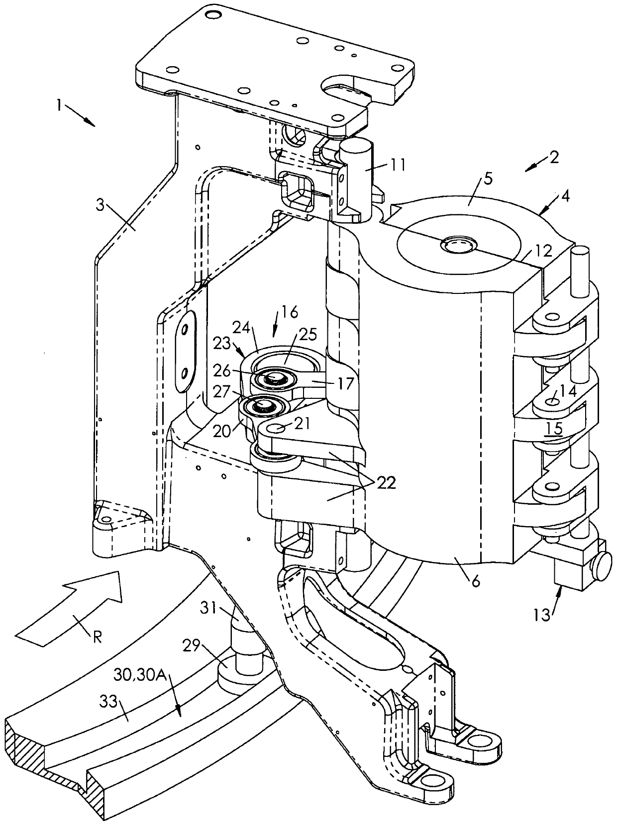
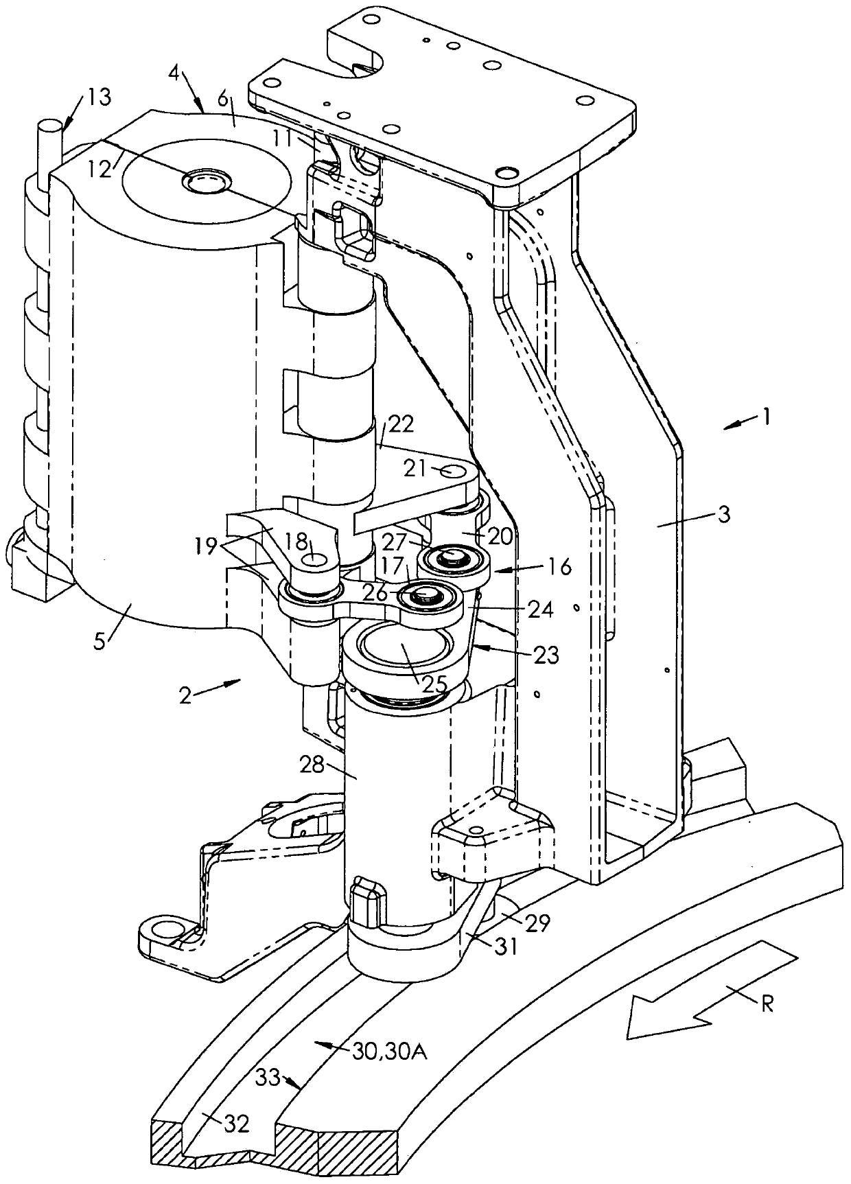
[0035] figure 1 , 2 Partially shown at and 5 is a manufacturing machine for manufacturing containers from blanks made of plastic, such as PET, by blow molding or blow drawing.

[0036] The machine 1 comprises a turntable and a series of molding units 2 mounted star-shaped on the turntable at its periphery. In the following, the terms “outer” and “front” mean a location away from the axis of rotation of the machine 1 , while conversely, the terms “inner” and “rear” mean a location relatively closer to the axis of rotation of the machine 1 . Arrow R shows the direction of rotation of the machine 1, which corresponds to the triangular direction (or counterclockwise direction) shown in the drawings. The terms "right" and "left" are used to indicate that similar structural or functional components are positioned upstream and downstream, respectively, in the direction of rotation of the machine 1, i.e. Figure 4 and 6 right and left of

[0037] Each molding unit 2 , of which on...


PUM


Abstract

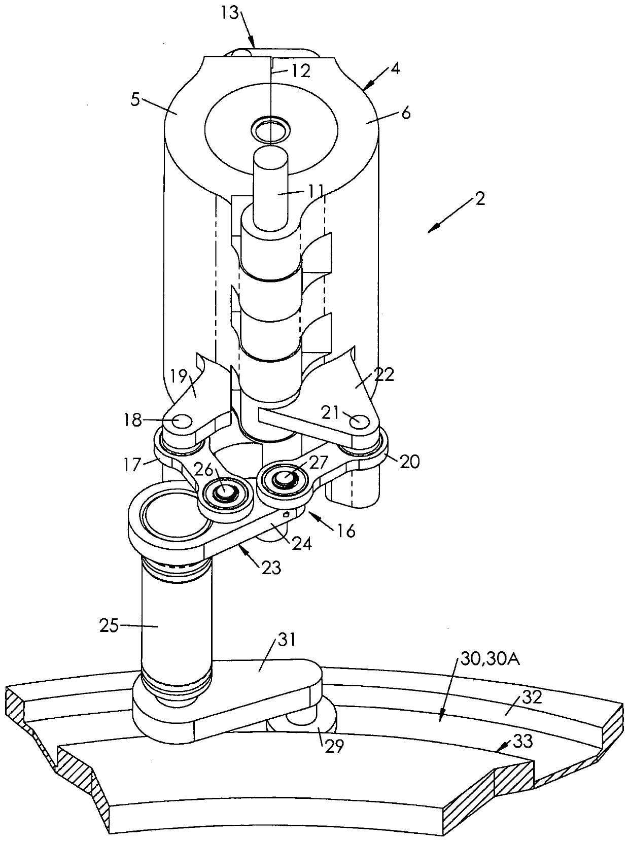
Control the mold opening and closing control mechanism (16) of the wallet mold (4), the wallet mold includes a right half mold (5) and a left half mold (6), and the right half mold and the left half mold surround The common hinge (11) is hingedly installed with each other, and the control mechanism includes: a right connecting rod (17), which is connected to the right half mold (5) in rotation around the right outer shaft (18) at the front end; the left connecting rod ( 20) which is connected in rotation at the front end to the left mold half (6) about a left outer shaft (21); an actuation system (23) which comprises a crank (24) about a hinge relative to the wallet mold (11) The fixed rotating shaft (25) is hinged, and the crank is connected to the right connecting rod (17) and the left connecting rod (20) in rotation around the right inner shaft (26) and the left inner shaft (27) spaced apart from each other respectively. ).

Description

technical field [0001] The invention relates to the control of the mold opening of the wallet type mold. Wallet molds generally consist of two mold halves, mounted one relative to the other about a common hinge, between a closed position and an open position, in which the mold halves rest one against the other, In the open position, the mold halves are angularly separated from each other. Background technique [0002] We often find such molds in manufacturing machinery that manufactures containers from plastic blanks by blow molding or stretch blow molding. In the open position, the mold half can be loaded with a blank, which is preheated to a temperature above the glass transition temperature of the material (approximately 80°C for polyethylene terephthalate PET plastic). The mold halves engage in the mold closing position and together define the cavity of the container to be formed. [0003] Molds are typically a series of similar molds mounted around the perimeter of a...

Claims


Application Information

Patent Timeline
Patent Type & Authority Patents(China)
IPC IPC(8): B29C49/56
CPCB29C49/56B29C49/06B29C49/36B29C2049/563B29C2049/4892B29C49/5602B29C49/561B29C2049/5664B29C2949/0715
Inventor J·米歇尔E·格罗森
Owner SIDEL PARTICIPATIONS SAS
Learn More