Rotary force transmission control mechanism and seat structure

A technology of rotational force transmission and control mechanism, applied in the field of rotational force transmission control mechanism and seat structure

Active Publication Date: 2019-07-05
DELTA TOOLING CO LTD
View PDF6 Cites 0 Cited by
  • Summary
  • Abstract
  • Description
  • Claims
  • Application Information

AI Technical Summary

Problems solved by technology

On the other hand, when a force to rotate the inner cylinder is applied from the pinion gear on the output side, each brake spring acts in the direction of expanding the diameter, and the inner cylinder cannot rotate due to contact with the inner peripheral surface of the outer cylinder.

Method used


Image

  • Rotary force transmission control mechanism and seat structure
  • Rotary force transmission control mechanism and seat structure
  • Rotary force transmission control mechanism and seat structure

Examples


Embodiment Construction

[0032] Hereinafter, the present invention will be described in more detail based on the illustrated embodiments.

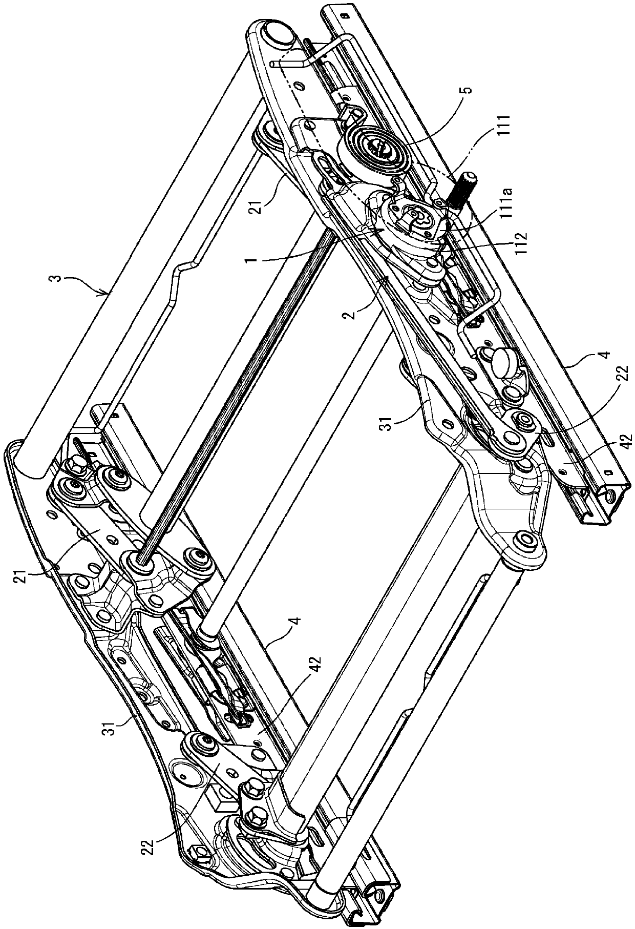
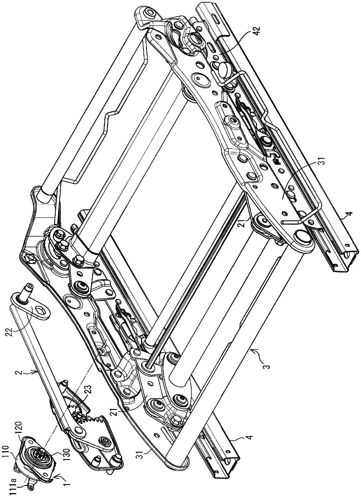
[0033] figure 1A cushion frame 3 having an elevating mechanism 2 incorporating a rotational force transmission control mechanism 1 according to an embodiment of the present invention is shown. The cushion frame 3 is supported by the upper rails 42 , 42 of the pair of sliders 4 , 4 . The lift mechanism 2 has front links 21 , 21 and rear links 22 , 22 arranged between the upper rails 42 , 42 and the side frames 31 , 31 constituting the cushion frame 3 . 42 The spiral spring 5 that biases the cushion frame 3 (side frames 31, 31) upward is configured to include the rotational force transmission control mechanism 1 of the present embodiment.

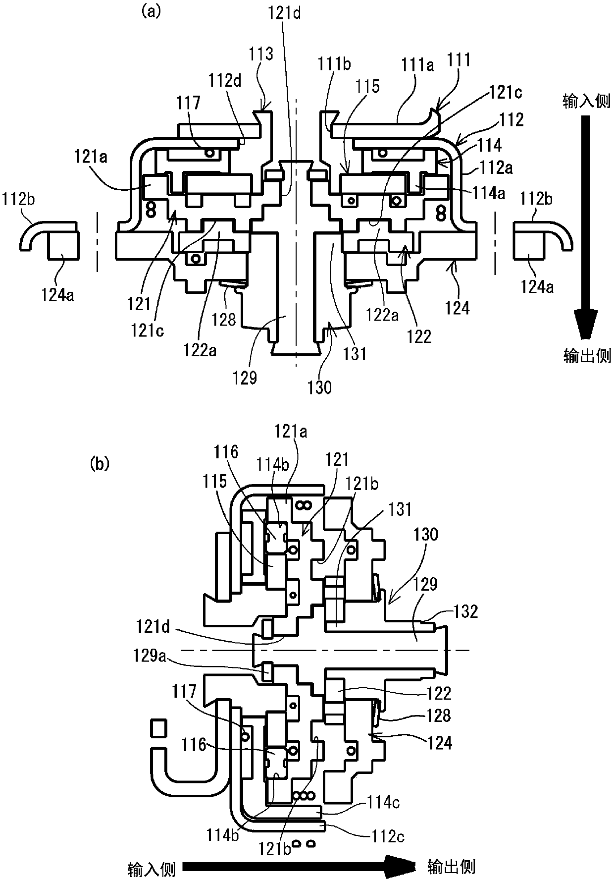
[0034] Such as Figure 2 ~ Figure 4 As shown, the rotational force transmission control mechanism 1 is configured to include a feed mechanism 110 , a rotation control unit 120 , and an output unit 130 . When an input torque f...


PUM


Abstract

The present invention more reliably suppresses output-side displacement than conventional mechanisms. The present invention is provided with a rotation control unit 120 that maintains a locked state when an input torque rotating a transfer mechanism 110 is not applied, and releases the locked state when the transfer mechanism 110 rotates. The rotation control unit 120 has an internal gear 124 and lock plates 123 that include outer teeth that can engage with inner teeth of the internal gear 124. When an input torque is not applied, the inner teeth of the internal gear 124 engage with the outer teeth of the lock plates 123, and when the transfer mechanism 110 is rotated, engagement between the inner teeth and the outer teeth is released. Thus, even when torque is applied from the output unit side, engagement between the inner teeth and the outer teeth is not released by the torque.

Description

technical field [0001] The present invention relates to a rotational force transmission control mechanism and a seat structure provided with the rotational force transmission control mechanism. Background technique [0002] For example, as shown in Patent Document 1, as an elevating mechanism of a seat structure, the following mechanism is known: In the feeding mechanism (in Patent Document 1, it is configured to include an operating handle, a handle base, a lock base, a locked member, an operating When the shaft mechanism) rotates from the neutral position due to the input torque, the output part rotates, and the pinion gear and the sector gear connected to the output part rotate to raise and lower the seat cushion. [0003] In Patent Document 1, a brake drum for controlling transmission of input torque to the output portion is interposed between the feed mechanism and the output portion. The brake drum has an outer cylinder and an inner cylinder (in Patent Document 1, the...

Claims


Application Information

Patent Timeline
Patent Type & Authority Patents(China)
IPC IPC(8): B60N2/16A47C1/02A47C7/40B60N2/10B60N2/90
CPCB60N2/1615B60N2/167B60N2/168B60N2/938B60N2/943B60N2/933B60N2/224F16H31/002G05G5/18G05G5/24
Inventor 朝居辉三藤田悦则井上胜博
Owner DELTA TOOLING CO LTD
Why Eureka
Try Eureka