
Vertical full-rotation shuttle

A full rotary hook, vertical technology, used in textiles and papermaking, sewing equipment, ferrule mechanism for sewing machines, etc., can solve problems such as yarn breakage and winding, and achieve the effect of preventing yarn breakage and yarn winding.

Active Publication Date: 2017-08-18
HIROSE MFG
View PDF6 Cites 0 Cited by
  • Summary
  • Abstract
  • Description
  • Claims
  • Application Information

AI Technical Summary

Problems solved by technology

Therefore, when the next sewing operation starts, the lower yarn in the gap cannot be drawn out smoothly and becomes entangled, causing problems such as yarn breakage and yarn winding.

Method used


Image

  • Vertical full-rotation shuttle
  • Vertical full-rotation shuttle
  • Vertical full-rotation shuttle

Examples


Embodiment Construction

[0051] Preferred embodiments of the present invention will be described in detail below with reference to the accompanying drawings.

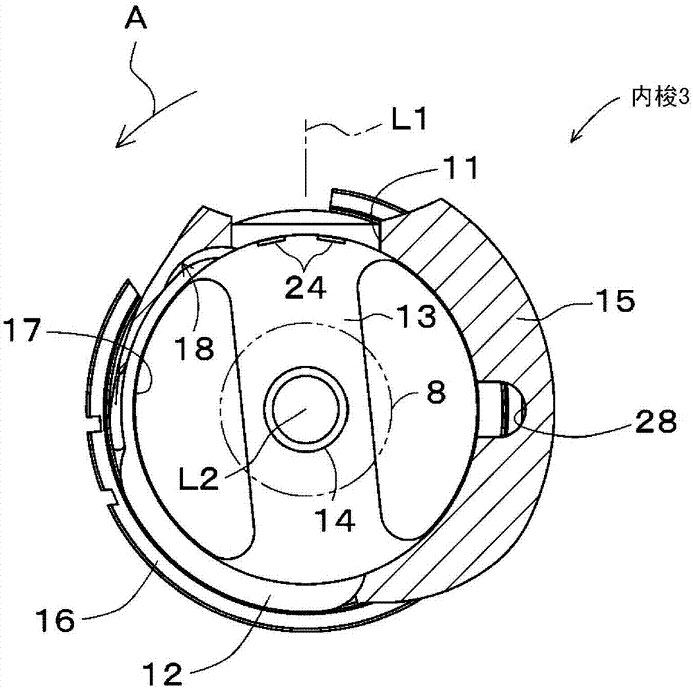
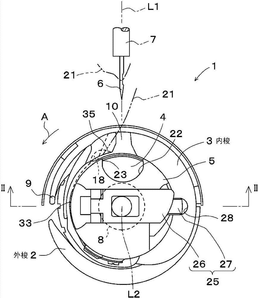
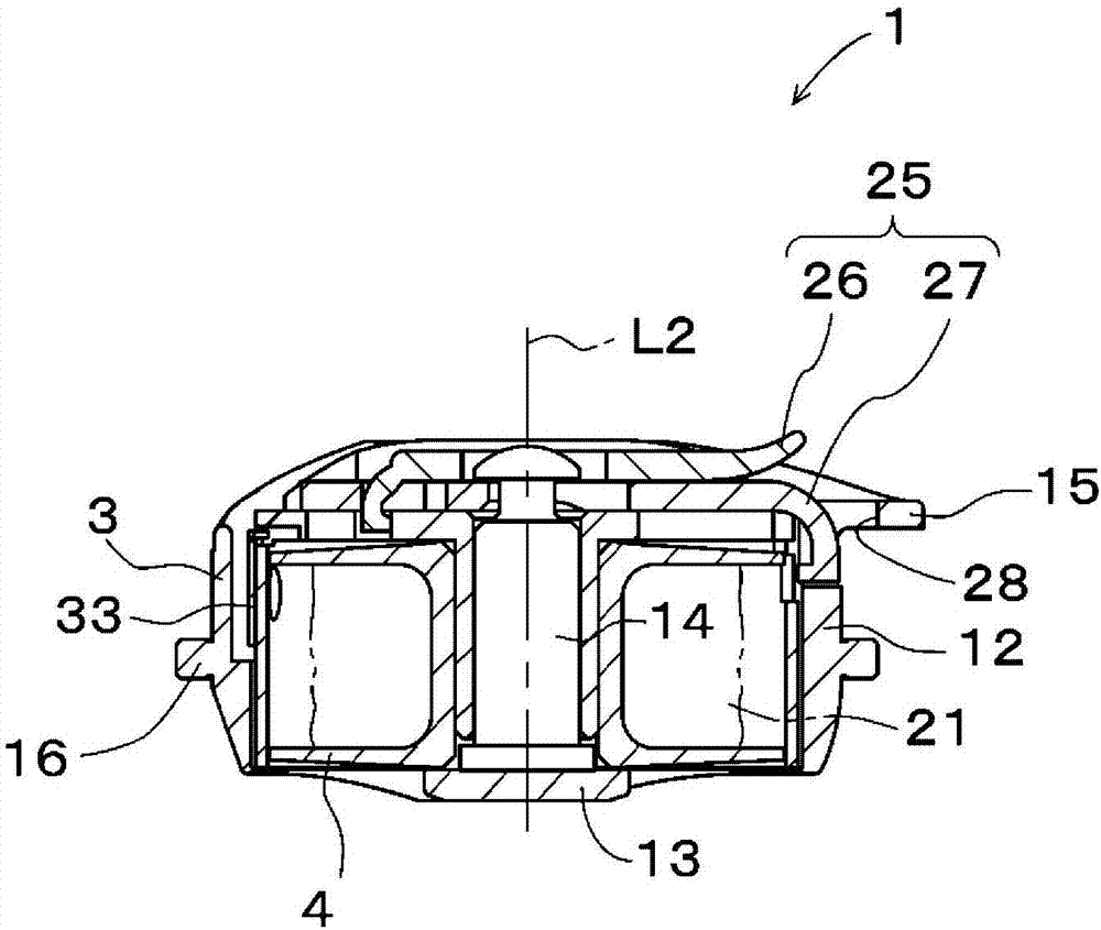
[0052] figure 1 It is a cross-sectional view of the inner hook 3 included in the vertical full rotary hook 1 according to one embodiment of the present invention viewed from the front side, figure 2 is the front view of vertical rotary hook 1, image 3 for from figure 2 The sectional view of the vertical full rotary hook 1 is seen on the section line II-II. Figure 4 It is a three-dimensional view of inner shuttle 3, Figure 5 It is the left side view of inner shuttle 3. figure 1 means from Figure 5 The section line I-I of the section line I-I sees the section of inner shuttle 3.

[0053] The vertical full-rotating hook 1 of this embodiment includes an outer hook 2 , an inner hook 3 , a bobbin 4 and a bobbin case 5 . The outer shuttle 2 is fixed to a lower shaft 8 that is rotationally driven in the direction of arrow A around a rotation...


PUM


Abstract

In order to prevent thread breakage and incidental looping, a thread escape recess (18) recessed outward in the radial direction relative to an imaginary cylindrical surface inscribed in an internal peripheral part (17) of an inside shuttle (3) is provided adjacent to the downstream side in the rotation direction (A) of a needle location hole (11).

Description

technical field [0001] The present invention relates to a vertical full-rotating hook provided in a sewing machine. Background technique [0002] A conventional vertical full rotary hook is described in Patent Document 1, for example. This prior art vertical full-rotating hook includes: an outer hook fixed to the lower shaft of the sewing machine and having a tip portion, an inner hook held in a state of being housed in the outer hook, and a bobbin detachably attached to the inner hook. Cover, and the bobbin that winds the lower yarn and is housed in the bobbin cover. [0003] When the sewing operation of the sewing machine starts, the lower shaft is rotated and driven in a predetermined rotational direction around a horizontal rotational axis, and the sewing needle is repeatedly moved towards and away from the rotational axis along an axis perpendicular to the rotational axis of the lower shaft. The suture inserted into the sewing needle is caught by the tip of the shuttl...

Claims


Application Information

Patent Timeline
Patent Type & Authority Applications(China)
IPC IPC(8): D05B57/14
CPCD05B57/14D05B57/28
Inventor 畑中润
Owner HIROSE MFG
Learn More