Workpiece clamping device with oscillating drive and vacuum supporting functions and relevant vacuum clamp

A technology of swing drive and workpiece clamping, applied in positioning devices, metal processing machinery parts, clamping and other directions, can solve the problems of high structural cost and sealing, and achieve the effect of simple processing and precise processing

Inactive Publication Date: 2017-08-22
英格博格马夸特
View PDF8 Cites 3 Cited by
  • Summary
  • Abstract
  • Description
  • Claims
  • Application Information

AI Technical Summary

Problems solved by technology

The disadvantage of this arrangement is the higher constructional costs in the case of the supply of hydraulic medium to the workholding device and the sealing problems associated therewith

Method used


Image

  • Workpiece clamping device with oscillating drive and vacuum supporting functions and relevant vacuum clamp
  • Workpiece clamping device with oscillating drive and vacuum supporting functions and relevant vacuum clamp
  • Workpiece clamping device with oscillating drive and vacuum supporting functions and relevant vacuum clamp

Examples


Embodiment Construction

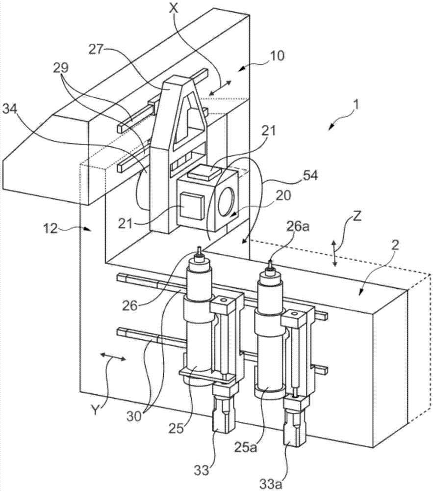
[0039] exist figure 1 The workpiece processing machine 1 is shown in perspective in the middle, which can be varied in various embodiments.

[0040] Only shown as a preferred exemplary embodiment is that the approximately square component 2 supports an L-shaped middle part 12 , on which the square upper part 10 rests, which is chamfered for weight-saving reasons.

[0041] On the front side of the base part 2 , in the region of the guide rail 30 , a carriage for the displacement drive of the two tool spindles 25 , 25 a arranged next to each other is formed. Each tool spindle 25 , 25 a is driven by a separate drive motor 33 , 33 a and accordingly there is a separate drive for the machining spindle 26 , 26 a. The guide rail 30 is oriented in the Y direction.

[0042] At the front side of the upper part 10 , an L-shaped beam 27 is arranged in the region of the guide rail 29 , at its lower free end a workpiece clamping device 20 according to the invention is arranged about the so...


PUM


Abstract

The invention provides a workpiece clamping device (20) with an oscillating drive function, and the workpiece clamping device (20) is used for machining a workpiece (21) in a workpiece machining device (1). The workpiece clamping device (20) is provided with a plurality of vacuum clamping plates (6 and 7) distributed on different planes on the circumference, and the vacuum clamping plates (6 and 7) are connected with a vacuum clamp (5) in an airtight mode.

Description

technical field [0001] The object of the invention is a pivotally driven vacuum-supported workpiece clamping device. Such workpiece holding devices are also referred to as workpiece carriers. Background technique [0002] In the case of workpiece processing machines, the problem arises that workpieces held there in a workpiece holding device are machined and that a particularly simple and operationally reliable clamping possibility should be available. [0003] DE 101 24 315 C1 describes a vacuum clamping device with a suction gripper suitable for holding a workpiece to be processed by vacuum. However, suction grippers cannot grip multiple workpieces. [0004] DE 199 61 773 C1 describes two rotatably driven workpiece clamping devices, each of which is suitable for receiving a workpiece. The respective workpiece is clamped by spring force and the actuation of the clamping spring takes place hydraulically. Thus, two adjacent workpieces can be welded to one another in the r...

Claims


Application Information

Patent Timeline
Patent Type & Authority Applications(China)
IPC IPC(8): B23B31/30
CPCB23B31/307B23Q3/061B23Q3/088
Inventor 乌韦·马夸特
Owner 英格博格马夸特
Why Eureka
Try Eureka