Automatic assembly device

A technology of automatic assembly and equipment, applied in the field of automation, can solve the problems of poor accuracy, low efficiency, labor, etc., and achieve the effect of good accuracy and high assembly efficiency

Pending Publication Date: 2017-08-22
苏州市中智远创机械科技有限公司
View PDF6 Cites 1 Cited by
  • Summary
  • Abstract
  • Description
  • Claims
  • Application Information

AI Technical Summary

Problems solved by technology

However, in the prior art, when assembling the nail shank and the nail sleeve, the assembly is mainly done manually, which has low efficiency and poor precision.

Method used


Image

  • Automatic assembly device
  • Automatic assembly device
  • Automatic assembly device

Examples


Embodiment Construction

[0022] The present invention will be described in detail below in conjunction with the implementations shown in the drawings, but it should be noted that these implementations are not limitations of the present invention, and those of ordinary skill in the art based on the functions, methods, or structural changes made by these implementations Equivalent transformations or substitutions all fall within the protection scope of the present invention.

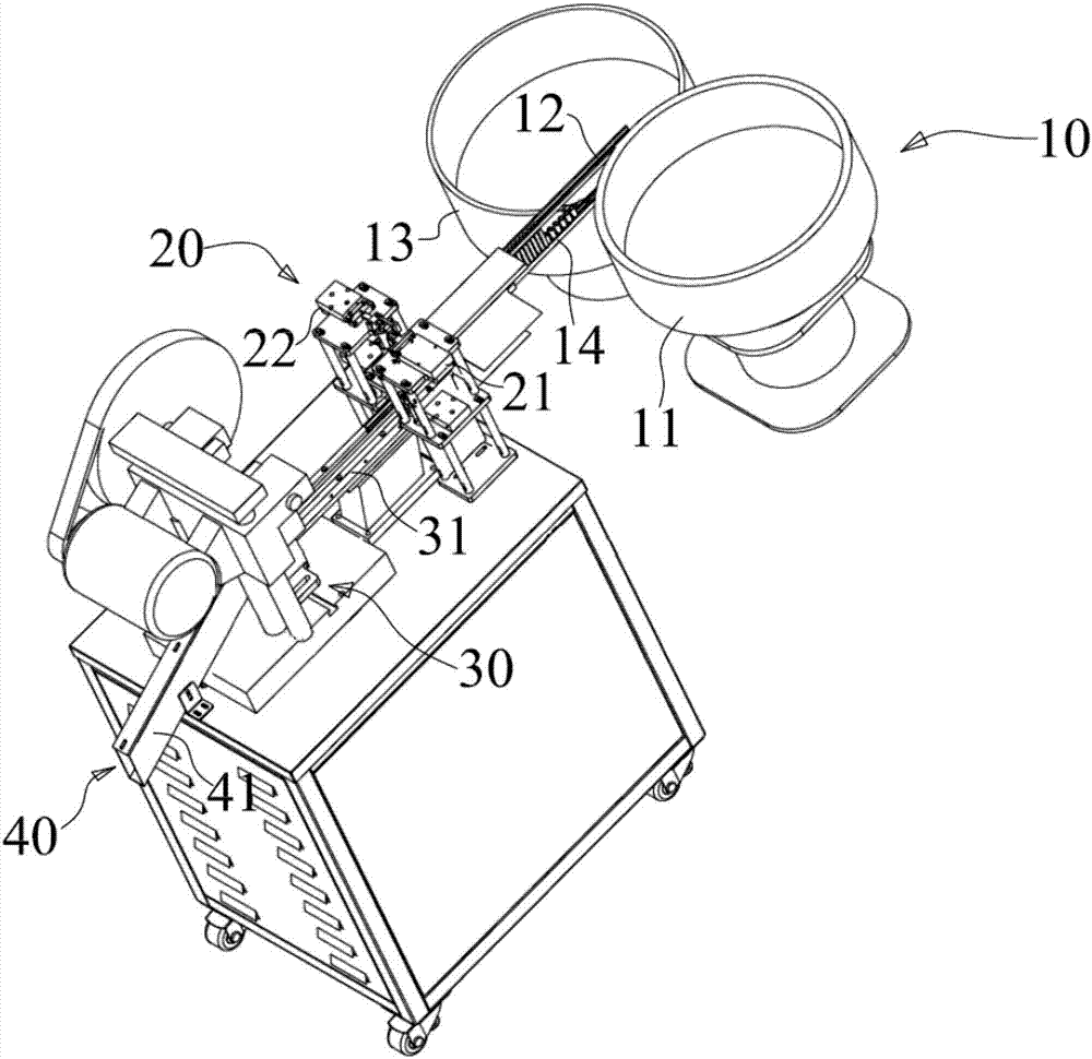
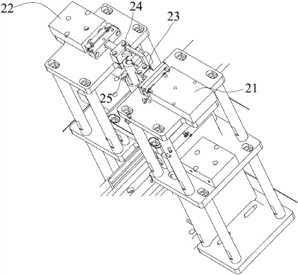
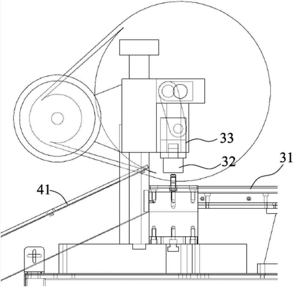
[0023] like figure 1 As shown, the automatic assembly equipment 1 of the present invention is used for the assembly of nail rods and nail sleeves. Specifically, the automatic assembly equipment includes sequentially arranged: feeding station 10, fitting station 20, pressing station 30 and output Material station 40.

[0024] The feeding station 10 is used to transport the nail rod and the nail sleeve to the fitting station 20 for fitting. Specifically, the feeding station 10 includes a first vibration plate 11 and a first guide ...


PUM


Abstract

The invention provides an automatic assembly device. The automatic assembly device comprises a feeding station, a sleeving station, a pressing-fit station and a discharging station which are sequentially arranged. The feeding station comprises a first vibration disc and a first guide rail and further comprises a second vibration disc and a second guide rail. The first guide rail used for conveying nail rods is located above the second guide rail used for conveying nail sleeves. The sleeving station comprises a first air cylinder and a second air cylinder which are oppositely arranged and do not synchronously work. The first air cylinder applies fixing acting force onto the nail rods conveyed through the first guide rail, and the second air cylinder applies pushing force which enables the nail rods to fall off onto the nail rods conveyed through the first guide rail. The pressing-fit station comprises a stamping head and a power mechanism used for driving the stamping head to conduct stamping. The discharging station comprises an obliquely-arranged discharging slide rail with one end being connected with the pressing-fit station. According to the automatic assembly device, automatic assembly of the nail rods and the nail sleeves can be achieved, assembly efficiency of the automatic assembly device is high, precision is good, and the requirements of modern industry production are sufficiently met.

Description

technical field [0001] The invention relates to the technical field of automation, in particular to an automatic assembly device for assembling a nail rod and a nail sleeve. Background technique [0002] Nail rods and nail sleeves are industrially widely used components. When the above-mentioned nail rod and nail sleeve are assembled, the nail sleeve is set on the nail rod and fixed by pressing. However, in the prior art, when assembling the nail shank and the nail sleeve, the assembly is mainly done manually, which has low efficiency and poor precision. [0003] Therefore, in view of the above problems, it is necessary to propose a further solution. Contents of the invention [0004] The object of the present invention is to provide an automatic assembly equipment to overcome the shortcomings in the prior art. [0005] In order to achieve the above-mentioned purpose of the invention, the present invention provides an automatic assembly device, which is used for the ass...

Claims


Application Information

Patent Timeline
IPC IPC(8): B23P19/027B23P19/00
CPCB23P19/004B23P19/027
Inventor 谢凯通
Owner 苏州市中智远创机械科技有限公司
Why Eureka
Try Eureka