Automatic calibration device of robot monocular vision guiding system

An automatic calibration and monocular vision technology, applied to manipulators, program-controlled manipulators, manufacturing tools, etc., can solve problems such as long time-consuming and complicated calibration process

Inactive Publication Date: 2017-08-22
SHANGHAI ELECTRICGROUP CORP
View PDF3 Cites 27 Cited by
  • Summary
  • Abstract
  • Description
  • Claims
  • Application Information

AI Technical Summary

Problems solved by technology

[0011] The current calibration method of robot vision guidance system has the disadvantages of complicated calibration process and long time-consuming

Method used


Image

  • Automatic calibration device of robot monocular vision guiding system
  • Automatic calibration device of robot monocular vision guiding system
  • Automatic calibration device of robot monocular vision guiding system

Examples


Embodiment Construction

[0051] In describing the embodiments of the present invention, it should be understood that the terms "upper", "lower", "front", "rear", "left", "right", "vertical", "horizontal", "top ", "Bottom", "Inner", "Outer", "Clockwise", "Counterclockwise" and other indicated orientations or positional relationships are based on the orientations or positional relationships shown in the drawings, and are only for the convenience of describing the present invention and Simplified descriptions, rather than indicating or implying that the device or element referred to must have a particular orientation, be constructed and operate in a particular orientation, and thus should not be construed as limiting the invention. The attached drawings are schematic diagrams or conceptual diagrams, and the relationship between the thickness and width of each part, as well as the proportional relationship between each part, etc., are not completely consistent with their actual values.

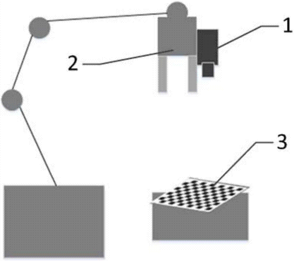
[0052] The device...


PUM


Abstract

The invention provides an automatic calibration device of a robot monocular vision guiding system. The automatic calibration device of the robot monocular vision guiding system comprises a mechanical arm driving module, a camera communication module, an image acquisition module, a camera calibration module, a hand-eye calibration module and an interactive interface, wherein the image acquisition module is used for managing movement of a mechanical arm during calibration and acquiring calibration plate images shot by a camera; the camera calibration module transfers a calibration plate image set in the image acquisition module, so that corresponding camera internal reference, external reference and lens distortion coefficients are generated; and the hand-eye calibration module transfers the calibration plate image set in the image acquisition module and the corresponding camera internal reference, external reference and lens distortion coefficients in the camera calibration module, and a transformation relation between a coordinate system of the camera and a coordinate system of the tail end of the mechanical arm is obtained by calculation.

Description

technical field [0001] The invention relates to the field of robot monocular vision guidance, in particular to a calibration method for a robot monocular vision guidance system. Background technique [0002] Machine vision is a rapidly developing branch of artificial intelligence. Simply put, machine vision is the use of machines instead of human eyes for measurement and judgment. The machine vision system converts the ingested target into an image signal through machine vision products, transmits it to a dedicated image processing system, obtains the shape information of the captured target, and converts it into a digital signal according to the pixel distribution, brightness, color and other information; the image system Various calculations are performed on these signals to extract the characteristics of the target, and then the on-site equipment actions are controlled according to the results of the discrimination. [0003] With the advancement of Industry 4.0, the pro...

Claims


Application Information

Patent Timeline
Patent Type & Authority Applications(China)
IPC IPC(8): B25J9/16
CPCB25J9/1671
Inventor 徐胤袁浩巍李智
Owner SHANGHAI ELECTRICGROUP CORP
Why Eureka
Try Eureka