
Electro-hydraulic control hand braking system

An electro-hydraulic control and hand brake technology, applied in the field of hydraulic components, can solve the problems that the service brake and hand brake cannot be independent, cannot be equipped with dry bridge, and the valve block is complicated, and achieves mature manufacturing technology, low cost, Wide range of effects

Pending Publication Date: 2017-08-22
XCMG CONSTR MACHINERY
View PDF6 Cites 4 Cited by
  • Summary
  • Abstract
  • Description
  • Claims
  • Application Information

AI Technical Summary

Problems solved by technology

The gearbox with full hydraulic wet brake can only be equipped with a wet bridge, and the gearbox uses electro-hydraulic control caliper brakes. However, the valve block of the electro-hydraulic control system is very complicated, and multiple accumulators are filled with fluid at the same time. It is an integrated filling valve, and the cost is high. At the same time, it cannot be equipped with a dry bridge, that is, the service brake and hand brake cannot be independent. It is an integrated braking solution.

Method used


Image

  • Electro-hydraulic control hand braking system
  • Electro-hydraulic control hand braking system

Examples


Embodiment Construction

[0020] The present invention will be further described below in conjunction with accompanying drawing.

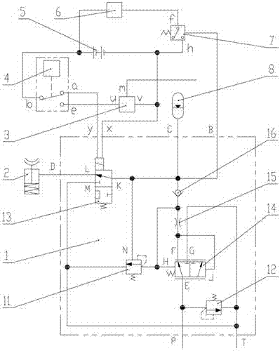
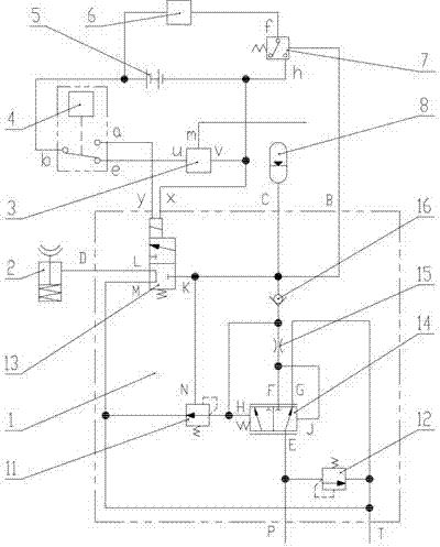
[0021] Such as figure 1 As shown, an electro-hydraulic control hand brake system of the present invention includes an oil circuit system and an electric circuit system; the oil circuit system includes a hydraulic valve 1, a hand brake device 2 and an accumulator 8, and the C port of the hydraulic valve 1 is connected to the accumulator The inlet of the energy device 8, the D port of the hydraulic valve 1 is connected to the inlet of the hand brake device 2; the circuit system includes the power supply 5, the first signal device 3, the hand brake switch 4, the second signal device 6 and the pressure relay 7; the circuit Hand brake alarm connection: the positive pole of the power supply 5 is connected to the terminal b of the hand brake switch 4, the terminal b of the hand brake switch 4 is connected to the terminal a in advance, and the terminal a of the hand brake switch 4 ...


PUM


Abstract

The invention discloses an electro-hydraulic control hand braking system which comprises an oil line system and a circuit system, wherein the oil line system comprises a hydraulic valve, a hand braking device and an accumulator, a port C of the hydraulic valve is connected with the inlet of the accumulator, and a port D of the hydraulic valve is connected with the inlet of the hand braking device; the circuit system comprises a power source, a first signal device, a hand braking switch, a second signal device and a pressure relay; the positive pole of the power source is connected with a terminal b of the hand braking switch, the other line of the positive pole of the power source is connected with an end f of the pressure relay through the second signal device, and the negative pole of the power source is connected with a terminal x of the hydraulic valve; a terminal a of the hand braking switch is connected with a terminal y of the hydraulic valve, and a terminal e of the hand braking switch is connected with an end u of the first signal device; an end v of the first signal device is connected with the negative pole of the power source; and an end h of the pressure relay is connected with the negative pole of the power source. The electro-hydraulic control hand braking system disclosed by the invention is independent of a travel braking system, can be equipped with a dry type bridge or a wet type bridge, and is simple in principle, low in cost and reliable in work.

Description

technical field [0001] The invention relates to a hydraulic component on a loader, in particular to an electro-hydraulic control hand brake system. Background technique [0002] When the loader is equipped with a dry bridge, the service brake scheme is air top oil brake, the hand brake scheme uses air circuit to control the stroke of the flexible shaft, and performs drum brake on the output end of the gearbox, and the hand brake The air circuit and the foot brake air circuit are not independent; and when the output end of the gearbox is not a drum brake, but a hydraulic control caliper disc brake, the flexible shaft brake cannot be installed. Hydraulic control caliper disc hand brake: Under the action of the electric signal device, a certain amount of pressure oil can be input to release the hand brake device. When the power is cut off or the hand brake switch is pressed, the pressure oil is connected to the fuel tank, and the hand brake Under the pressure of the spring, th...

Claims


Application Information

Patent Timeline
Patent Type & Authority Applications(China)
IPC IPC(8): B60T13/14B60T13/68B60T7/08
CPCB60T13/14B60T13/686B60T7/085
Inventor 张永胜郭军胜王小虎李凯张爱霞章珍钟俊伟武俊燕赵锦
Owner XCMG CONSTR MACHINERY
Learn More