Blast-furnace process feeding equipment

A technology of feeding equipment and blast furnace smelting, applied in the direction of bell and funnel arrangement, etc., can solve the problems of low input efficiency of feeding equipment, difficulty in improving the heating efficiency of smelting raw materials, and easy adhesion of smelting raw materials on the wall of feeding equipment, etc. To achieve the effect of ensuring the output rate and preventing sticking

Inactive Publication Date: 2017-08-22
林芬兰
View PDF0 Cites 5 Cited by
  • Summary
  • Abstract
  • Description
  • Claims
  • Application Information

AI Technical Summary

Problems solved by technology

[0005] The present invention overcomes the shortcomings of the traditional feeding method of blast furnace smelting feeding equipment, smelting raw materials are easy to adhere to the wall of feeding equipment, which makes it difficult to fully utilize smelting raw materials, the input efficiency of feeding equipment is low, and it is difficult to improve the subsequent heating efficiency of smelting raw materials. , the technical problem to be solved by the present invention is to provide a blast furnace smelting feeding equipment

Method used


Image

  • Blast-furnace process feeding equipment
  • Blast-furnace process feeding equipment
  • Blast-furnace process feeding equipment

Examples


Embodiment 1

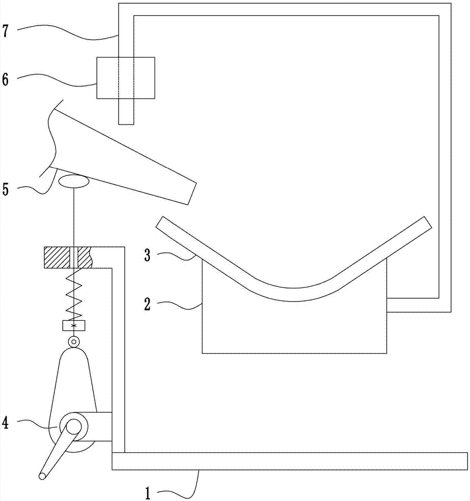
[0031] A blast furnace smelting feeding equipment, such as Figure 1-5 As shown, it includes a bottom plate 1, a heating box 2, a heating pot 3, a vibration device 4, a feed hopper 5, a crushing device 6 and a top bracket 7. Bracket 7, the lower end of the left side of the top bracket 7 is provided with a crushing device 6, the lower end of the right side of the top bracket 7 is connected with a heating box 2, a heating pot 3 is arranged above the heating box 2, and a feeding hopper 5 is arranged on the upper left side of the heating pot 3. The feeding hopper 5 is arranged below the pulverizing device 6 and above the vibrating device 4 .

Embodiment 2

[0033] A blast furnace smelting feeding equipment, such as Figure 1-5As shown, it includes a bottom plate 1, a heating box 2, a heating pot 3, a vibration device 4, a feed hopper 5, a crushing device 6 and a top bracket 7. Bracket 7, the lower end of the left side of the top bracket 7 is provided with a crushing device 6, the lower end of the right side of the top bracket 7 is connected with a heating box 2, a heating pot 3 is arranged above the heating box 2, and a feeding hopper 5 is arranged on the upper left side of the heating pot 3. The feeding hopper 5 is arranged below the pulverizing device 6 and above the vibrating device 4 .

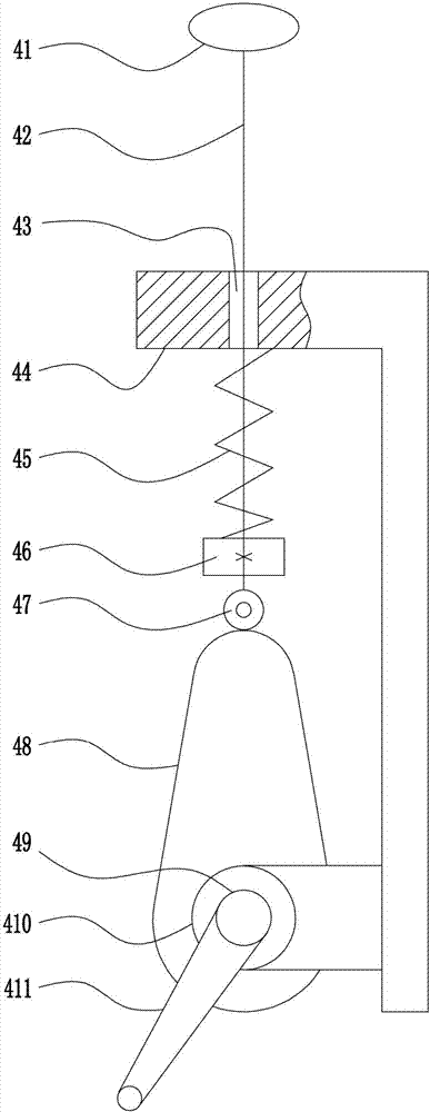
[0034] The vibrating device 4 includes a vibrating hammer 41, a lifting rod 42, an L-shaped guide plate 44, a first elastic member 45, a block 46, a contact wheel 47, a cam 48, a first rotating shaft 49, a first bearing seat 410 and a handle 411, The left end of the bottom plate 1 top is connected with an L-shaped guide plate 44, and the top...

Embodiment 3

[0036] A blast furnace smelting feeding equipment, such as Figure 1-5 As shown, it includes a bottom plate 1, a heating box 2, a heating pot 3, a vibration device 4, a feed hopper 5, a crushing device 6 and a top bracket 7. Bracket 7, the lower end of the left side of the top bracket 7 is provided with a crushing device 6, the lower end of the right side of the top bracket 7 is connected with a heating box 2, a heating pot 3 is arranged above the heating box 2, and a feeding hopper 5 is arranged on the upper left side of the heating pot 3. The feeding hopper 5 is arranged below the pulverizing device 6 and above the vibrating device 4 .

[0037] The vibrating device 4 includes a vibrating hammer 41, a lifting rod 42, an L-shaped guide plate 44, a first elastic member 45, a block 46, a contact wheel 47, a cam 48, a first rotating shaft 49, a first bearing seat 410 and a handle 411, The left end of the bottom plate 1 top is connected with an L-shaped guide plate 44, and the to...


PUM


Abstract

The invention relates to feeding equipment, in particular to blast-furnace process feeding equipment. The technical problem to be solved is to provide blast-furnace process feeding equipment, to solve the problem, the blast-furnace process feeding equipment is provided. The blast-furnace process feeding equipment comprises a base plate, a heating box, a heating kettle, a vibrating device, a feeding hopper and the like; the vibrating device is arranged at the left end of the top of the base plate, a top supporting frame is arranged above the base plate, a smashing device is arranged on the lower end of the left side of the top supporting frame, the heating box is connected with the lower end of the right side of the top supporting frame, the heating kettle is arranged on the heating box, the feeding hopper is arranged above the left side of the heating kettle, and the feeding hopper is arranged below the smashing device and located above the vibrating device. According to the blast-furnace process feeding equipment, smashing of caked or solid smelting raw materials is achieved, the follow-up heating treatment of the smelting raw materials is accelerated, and meanwhile the vibrated feeding hopper can prevent the smelting raw materials from adhering to the wall of the feeding hopper.

Description

technical field [0001] The invention relates to a feeding device, in particular to a blast furnace smelting feeding device. Background technique [0002] Blast furnace smelting equipment refers to the equipment composed of blast furnace body, blast furnace dust collector, blast furnace blower, blast furnace hot blast stove, molten iron tank car, etc. Due to the good technical and economic indicators of blast furnace ironmaking, simple process, large production volume, high labor production efficiency, and low energy consumption, the iron produced by this method accounts for the vast majority of the world's total iron production. During blast furnace production, iron ore, coke, and flux for slagging are loaded from the top of the furnace, and preheated air is blown in from the tuyeres located at the lower part of the furnace along the periphery of the furnace. At high temperature, the carbon in the coke is burned with the oxygen blown into the air to generate carbon monoxide...

Claims


Application Information

Patent Timeline
Patent Type & Authority Applications(China)
IPC IPC(8): C21B7/20
CPCC21B7/20
Inventor 林芬兰
Owner 林芬兰
Why Eureka
Try Eureka