Dry type spiral vacuum pump

A vacuum pump and screw technology, which is applied in the field of vacuum pumps, can solve the problems of dry screw vacuum pump damage, waste of energy consumption, and reduced exhaust speed, and achieve the effects of avoiding waste of energy consumption, saving horsepower, and maintaining exhaust speed

Inactive Publication Date: 2017-08-22
德耐尔节能科技(上海)股份有限公司
View PDF5 Cites 2 Cited by
  • Summary
  • Abstract
  • Description
  • Claims
  • Application Information

AI Technical Summary

Problems solved by technology

[0003] The invention provides a dry-type screw vacuum pump, which effectively solves the problem of the existing dry-type screw vacuum pump in pumping out a large amount of water vapor or other condensable gases by installing a Lu-type booster pump and a dry-type screw vacuum pump to work together. When the low pressure is maintained, the exhaust speed will decrease, which will waste energy and cause damage to the dry screw vacuum pump itself.

Method used


Image

  • Dry type spiral vacuum pump
  • Dry type spiral vacuum pump

Examples


Embodiment

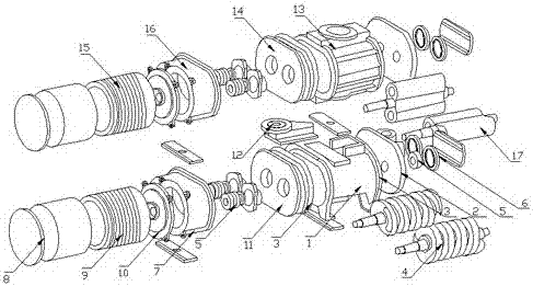
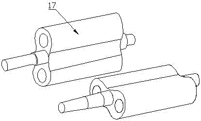
[0017] Such as Figure 1-2 As shown, a dry screw vacuum pump of the present invention includes a pump body 1, a high-pressure end plate 2, a rotor 4, a gear box 7 and a Lu-type booster pump 13. The pump body 1 is provided with a pair of counter-rotating rotors. 4. A high-pressure end plate 2 is sleeved on the shaft at one end of the rotor 4, a bearing 5 is installed on the high-pressure end plate 2 corresponding to the rotor 4, a high-pressure bearing cover 6 is installed outside the bearing 5, and the other end sleeve of the rotor 4 A low-pressure end plate 11 is provided. A bearing 5 is mounted on the outer side of the low-pressure end plate 11. The low-pressure end plate 11 is connected to a gear box 7 that is connected to a motor 9 and an oil seal 10. 9 is connected to a gear 8 at the top end, the gear 8 is arranged at one end of the pump body 1, a Lu-type booster pump 13 is connected to the top end of the pump body 1, and the Lu-type booster pump 13 is provided with a hous...


PUM


Abstract

The invention discloses a dry-type screw vacuum pump. A pair of counter-rotating rotors are arranged inside the pump body. A high-pressure end plate is sleeved on a rotating shaft at one end of the rotor. A bearing is installed on the high-pressure end plate corresponding to the rotor, and a high-voltage bearing cover is installed on the outer side of the bearing. , the other end of the rotor is set with a low-pressure end plate, bearings are installed on the outside of the low-pressure end plate, the low-pressure end plate is connected to a gear box, the gear box is connected to a motor and an oil seal, the top of the motor is connected to a gear, and the gear is set at one end of the pump body. The top of the pump body is connected with a Lu-style booster pump, and the Lu-style booster pump is provided with a housing end plate assembly, a gear box assembly, a motor assembly and a Lu-style booster pump rotor. The beneficial effects achieved by the present invention are: effective solution When the existing dry screw vacuum pump pumps out a large amount of water vapor or other condensable gases, the exhaust speed decreases under the condition of maintaining low pressure, which wastes energy and damages the dry screw vacuum pump itself.

Description

Technical field [0001] The invention relates to a screw vacuum pump, in particular to a dry screw vacuum pump, belonging to the field of vacuum pumps. Background technique [0002] Vacuum pump refers to a device or equipment that uses mechanical, physical, chemical, or physical-chemical methods to pump air from the pumped container to obtain a vacuum. Generally speaking, a vacuum pump is a device that uses various methods to improve, generate and maintain vacuum in a closed space. According to the working principle of vacuum pumps, vacuum pumps can basically be divided into two types, namely gas capture pumps and gas transmission pumps. It is widely used in metallurgy, chemical, food, electronic coating and other industries. Dry screw vacuum pump is a high-tech product with very high technical content. It is mainly used in high-purity vacuum process. The vacuum is extremely high and can adapt to harsh working conditions. It has the ability to extract condensable and particulate...

Claims


Application Information

Patent Timeline
Patent Type & Authority Applications(China)
IPC IPC(8): F04C25/02F04C23/00
CPCF04C25/02F04C23/003
Inventor 盛昌国
Owner 德耐尔节能科技(上海)股份有限公司
Why Eureka
Try Eureka