Multifunctional cascaded tail-end power output device

A power output, multi-functional technology, applied in the direction of coupling device, two-part connecting device, connecting device components, etc., can solve the problems of plugs that are difficult to meet different specifications, troublesome, and bulky sockets, and achieve simple structure and use. handy effect

Active Publication Date: 2017-08-22
万志伟
View PDF12 Cites 0 Cited by
  • Summary
  • Abstract
  • Description
  • Claims
  • Application Information

AI Technical Summary

Problems solved by technology

[0002]Traditional sockets are generally provided with multiple groups of jacks on a complete panel, the overall volume of the socket is large, and it is not easy to carry; and the existing sockets The distance between each two groups of jacks is difficult to meet the plugs of different specifications. It is very troublesome to replace different sockets to meet the needs.

Method used


Image

  • Multifunctional cascaded tail-end power output device
  • Multifunctional cascaded tail-end power output device
  • Multifunctional cascaded tail-end power output device

Examples


Embodiment approach

[0050] There are three implementation modes for the socket part of this embodiment, as follows:

Embodiment approach 1

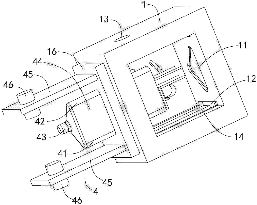
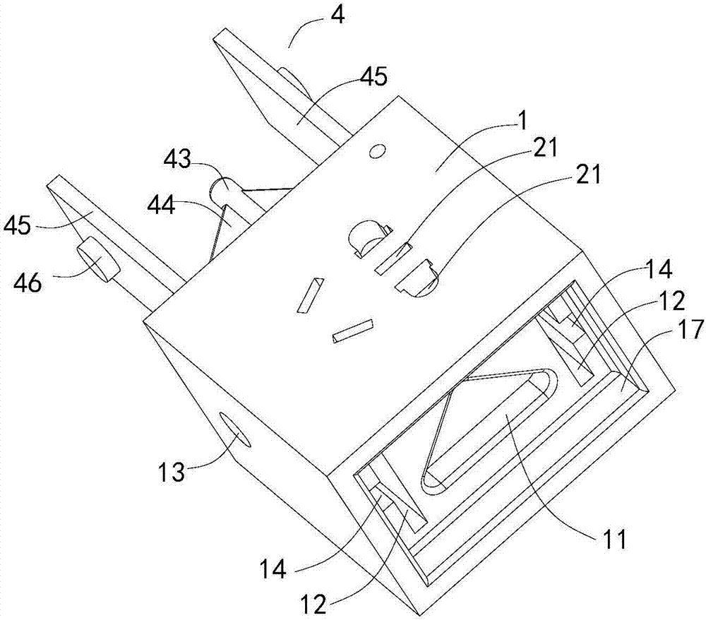
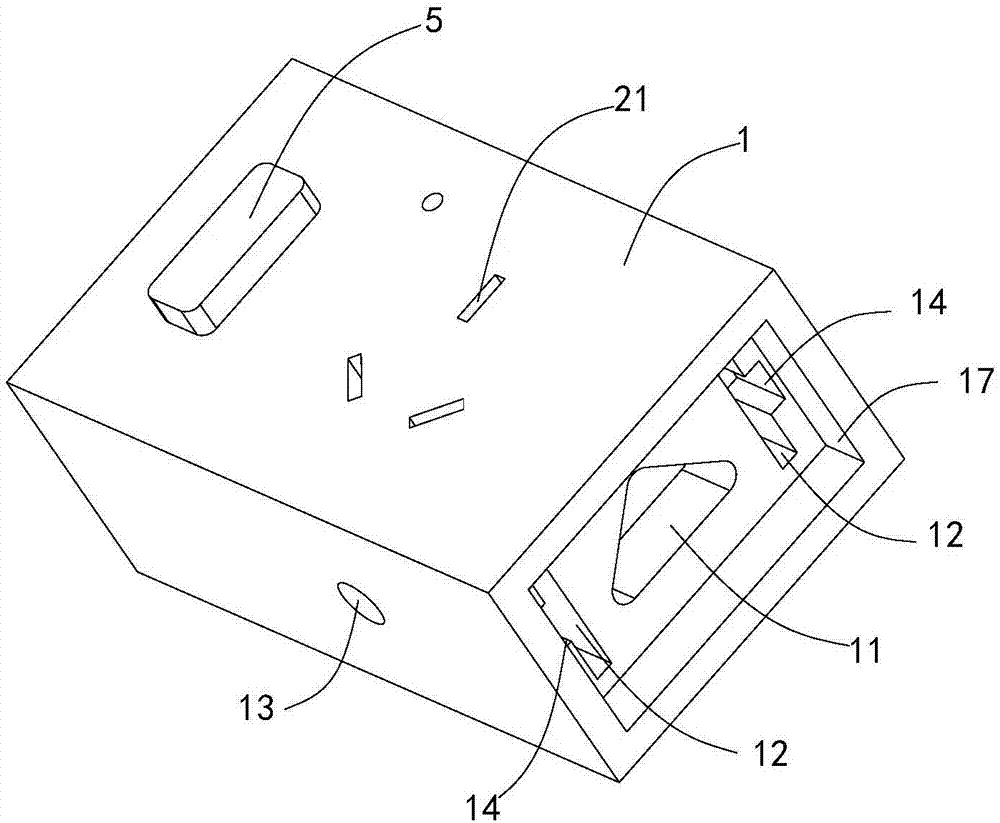
[0051] Embodiment 1, such as figure 1 and figure 2 As shown, the insertion part 4 of this embodiment may be a square columnar structure, a circular columnar structure or a polygonal columnar structure. The lengths of the zero wire connection post 41 , the live wire connection post 42 and the ground wire connection post 43 in this embodiment can be equal and fixed on the outer wall of the insertion post 44 , when the insertion post 44 is inserted into the first socket 11 , the neutral line connection post 41 , the live line connection post 42 and the ground line connection post 43 of the two connected cascaded socket units 1 are all connected to each other. The lengths of the zero wire connecting post, the live wire connecting post and the ground wire connecting post are all longer than the length of the plugging post.

[0052] Such as figure 1 As shown, in a preferred solution of this embodiment, the insertion post 44 is in the shape of a triangular prism, and the neutral ...

Embodiment approach 2

[0053] Embodiment 2, such as figure 1 and figure 2 As shown, the socket part 4 of this embodiment also includes a socket plate 45, one end of which is fixed to the head end or tail end of the cascaded socket unit 1 and is located at the socket One side of the column 44, the other end of which extends away from the cascaded socket unit 1; the socket includes a second socket 12, and the socket board 45 is adapted to be inserted into the second socket 12 Inside; the plug-in board 45 is arranged parallel to the side wall of the cascaded socket unit 1, and the side wall is provided with a slide groove 14 and a snap-in hole 13 or a snap-in groove. The plug-in board 45 A locking protrusion 46 is provided at a position close to the locking hole 13 or the locking groove, and the locking protrusion 46 is adapted to be locked in the locking hole 13 or the locking groove. The chute 14 is arranged along the axial direction of the insertion column 44, and the chute 14 communicates the lo...


PUM


Abstract

The invention relates to a multifunctional cascaded tail-end power output device which comprises multiple cascaded socket bodies, a plugging head and a power connection plug, and the power connection plug is connected with an external power supply. The top of each cascaded socket body is provided with a group of plug connection holes into which plugs of electrical appliances can be inserted, the multiple cascaded socket bodies are inserted in an end-to-end manner successively to form a patch board and are connected with one another, the power connection plug is plugged into the head end of the cascaded socket body at one end of the patch board and is connected with the corresponding cascaded socket body, and the plugging head is inserted into the tail end of the cascaded socket body at other end of the patch board and is connected with the corresponding cascaded socket body. The multiple cascaded socket bodies are arranged and can be combined at random according to requirements, the structure is simple, and use is convenient.

Description

technical field [0001] The invention relates to an electrical appliance, in particular to a multifunctional cascadable terminal power output device. Background technique [0002] Traditional sockets are generally provided with multiple sets of jacks on a complete panel. The overall volume of the socket is large and it is not easy to carry; and the distance between each two sets of jacks on the existing socket is difficult to meet different specifications. The plug needs to be replaced with a different socket to meet the needs, which is very troublesome. Contents of the invention [0003] The technical problem to be solved by the present invention is to provide a multifunctional cascadable terminal power supply output device for the deficiencies of the prior art. [0004] The technical solution of the present invention to solve the above-mentioned technical problems is as follows: a multi-functional cascadable terminal power output device, including multiple cascaded socke...

Claims


Application Information

Patent Timeline
Patent Type & Authority Applications(China)
IPC IPC(8): H01R13/514H01R13/627H01R13/71H01R13/713H01R13/73H01R24/00H01R27/00
CPCH01R13/514H01R13/6275H01R13/71H01R13/713H01R13/73H01R24/00H01R27/00
Inventor 万志伟
Owner 万志伟
Why Eureka
Try Eureka