
Pulling type electrical control cabinet

An electrical control cabinet, pull-out technology, applied in pull-out switch cabinets, electrical components, substation/distribution device enclosures, etc., can solve problems such as the influence of internal components, the reduction of the service life of components inside the control cabinet, and the entry of dust , to achieve the effect of reducing the service life

Pending Publication Date: 2017-08-22
CHINA SCI TIANGONG ELECTRICAL HLDG
View PDF5 Cites 4 Cited by
  • Summary
  • Abstract
  • Description
  • Claims
  • Application Information

AI Technical Summary

Problems solved by technology

[0003] However, most of the common electrical control cabinets on the market are equipped with unified cabinet doors on the surface of the cabinet body. In the actual use of this type of electrical control cabinet, if the internal components are damaged and need to be repaired, the entire cabinet needs to be repaired. When the door is opened for maintenance, the external dust will enter the control cabinet, and the internal components will be affected by the dust, which will greatly reduce the service life of the internal components of the control cabinet.

Method used


Image

  • Pulling type electrical control cabinet
  • Pulling type electrical control cabinet
  • Pulling type electrical control cabinet

Examples


Embodiment Construction

[0017] The following will clearly and completely describe the technical solutions in the embodiments of the present invention with reference to the accompanying drawings in the embodiments of the present invention. Obviously, the described embodiments are only some, not all, embodiments of the present invention. Based on the embodiments of the present invention, all other embodiments obtained by persons of ordinary skill in the art without making creative efforts belong to the protection scope of the present invention.

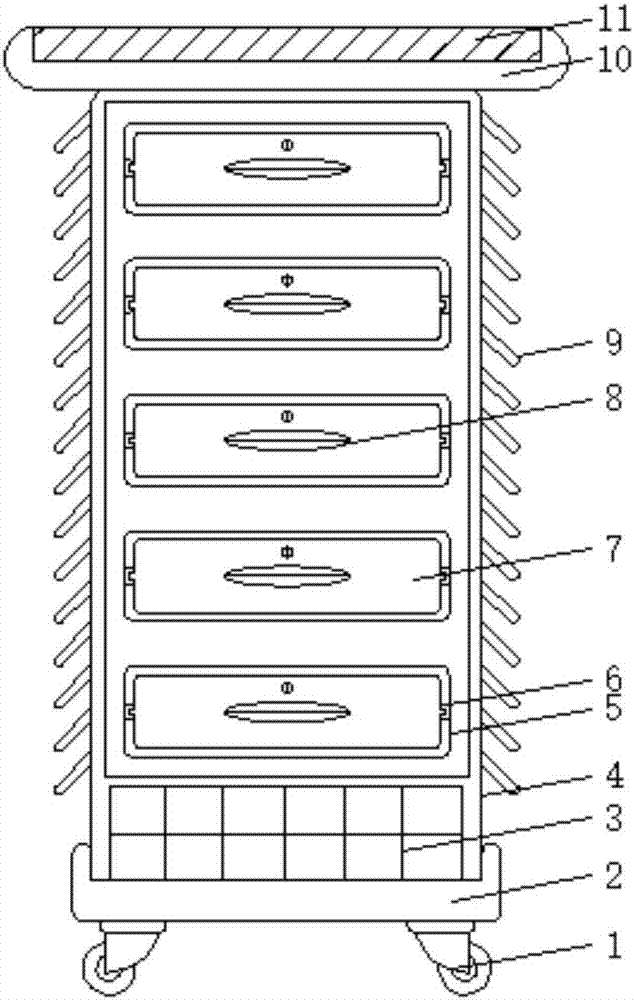
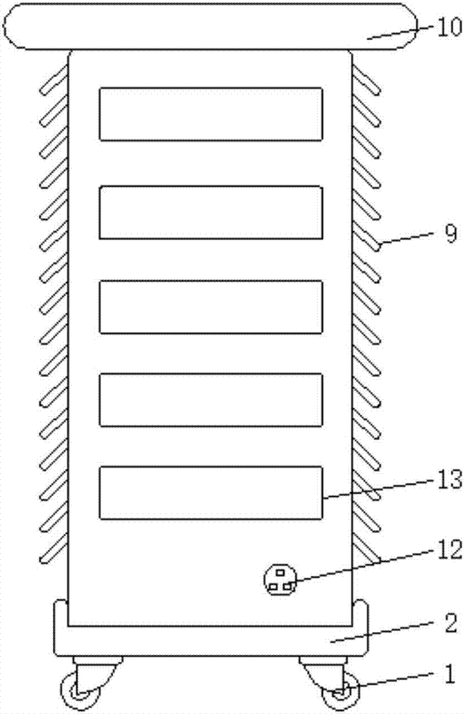
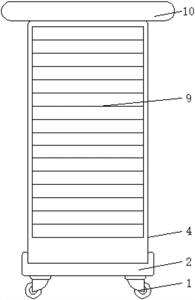
[0018] see Figure 1-5 , an embodiment provided by the present invention: a pull-out electrical control cabinet, including a moisture-proof base 2, a cabinet body 4, a pull-out installation groove 7, a heat dissipation louver 9 and a rain shelter 10, and the bottom of the moisture-proof base 2 is installed with The universal wheel 1 makes the control cabinet effectively moisture-proof, prevents the moisture from affecting the normal use of the internal compone...


PUM


Abstract

The invention discloses a pulling type electrical control cabinet. The electrical control cabinet comprises a moistureproof base, a cabinet body, a pulling installation groove, heat dissipation louvers and a rain shelter. Universal wheels are installed at the bottom of the moistureproof base. A solar cell board is installed on the upper end of the interior of the rain shelter. The heat dissipation louves are installed on two sides of the cabinet body. Dust filtering layers are arranged at the heat dissipation louves in the cabinet body. Sound isolation layers are arranged on the inner sides of the heat dissipation louves in the cabinet body. Sliding grooves are arranged in two sides in an installation cavity. The pulling installation groove is installed in the installation cavity between the sliding grooves. Heat dissipation holes are arranged in the surface of the pulling installation groove. LED sensing lamp plates are installed on two sides in the pulling installation groove. Storage battery sets are installed on the lower end of the interior of the cabinet body. According to the invention, through the structure equipped with a series of structures, the electrical control cabinet is quite easy to overhaul, and has waterproof and dustproof functions.

Description

technical field [0001] The invention relates to the technical field of electrical equipment, in particular to a pull-out electrical control cabinet. Background technique [0002] The electrical control cabinet is to assemble switchgear, measuring instruments, protective appliances and auxiliary equipment in a closed or semi-closed metal cabinet or on a screen width according to the requirements of electrical wiring. Equipment Security. During normal operation, the circuit can be connected or disconnected by means of a manual or automatic switch. Cut off the circuit or alarm with the help of protective electrical appliances in case of failure or abnormal operation. [0003] However, most of the common electrical control cabinets on the market are equipped with unified cabinet doors on the surface of the cabinet body. In the actual use of this type of electrical control cabinet, if the internal components are damaged and need to be repaired, the entire cabinet needs to be re...

Claims


Application Information

Patent Timeline
Patent Type & Authority Applications(China)
IPC IPC(8): H02B11/173H02B1/28H02B1/56H02B1/54
CPCH02B1/28H02B1/54H02B1/565H02B11/173
Inventor 张云龙阴加花张帆刘雅群马勇张世锦
Owner CHINA SCI TIANGONG ELECTRICAL HLDG
Learn More