Thin-wall corrugated pipe welding method and welding clamp

A welding method and welding fixture technology, applied in the field of machining and manufacturing, can solve the problems affecting welding efficiency and part qualification rate, burning through parts, bellows deformation, etc., so as to improve welding efficiency, avoid repair welding, and reduce deformation. Effect

Inactive Publication Date: 2017-08-25
HUNAN SOUTH GENERAL AVIATION ENGINE CO LTD
View PDF7 Cites 6 Cited by
  • Summary
  • Abstract
  • Description
  • Claims
  • Application Information

AI Technical Summary

Benefits of technology

This patented technology provides an improved way for joining different types of pipes without causing any damage or distortion that affects their quality. It involves fixing specially shaped tubular plates onto bases made from materials like steel plate before connecting them into specific shapes called flarepipes. These special plugs help prevent deformations such as cracks due to heat input. After inserting these plugs, they connect both ends through bolts tightly sealed within holes formed at one end of each plug. By applying pressure against this special type of fitting, there will form a strong connection secure enough to resist external forces applied thereto. Additionally, if needed, replacing damaged components may require rebuilding the entire assembly again instead of just having to replace only those affected areas. Overall, this new technique allows for more efficient use of resources and reduces costs associated with manufacturing processes.

Problems solved by technology

This patented technical solution involves finding ways to prevent damage caused from heat generated during laser joining processes on very small components like pipes made of aluminum foil due to their flexibility at room temperature.

Method used


Image

  • Thin-wall corrugated pipe welding method and welding clamp
  • Thin-wall corrugated pipe welding method and welding clamp
  • Thin-wall corrugated pipe welding method and welding clamp

Examples


Embodiment Construction

[0028] The following will clearly and completely describe the technical solutions in the embodiments of the present invention with reference to the accompanying drawings in the embodiments of the present invention. Obviously, the described embodiments are only some, not all, embodiments of the present invention. Based on the embodiments of the present invention, all other embodiments obtained by persons of ordinary skill in the art without making creative efforts belong to the protection scope of the present invention.

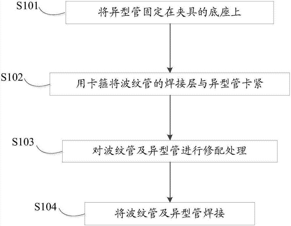
[0029] The thin-walled corrugated pipe welding method provided by the embodiment of the present invention includes:

[0030] S101: Fix the special-shaped tube on the base of the fixture.

[0031] To ensure the stability of the special-shaped tube, and to facilitate pressing the bellows on the special-shaped tube.

[0032] S102: Fasten the welding layer of the corrugated pipe and the special-shaped pipe with a clamp.

[0033] After pressing the corrugated pip...


PUM


Abstract

The invention discloses a thin-wall corrugated pipe welding method and welding clamp. The welding method includes the steps that a special-shaped pipe is fixed to a base of the clamp; a welding layer of a corrugated pipe and the special-shaped pipe are tightly clamped through a hoop; the corrugated pipe and the special-shaped pipe are subject to repairing and matching treatment; and the corrugated pipe and the special-shaped pipe are welded. By means action force of the hoop, the shape of the corrugated pipe can be effectively guaranteed, and the deformation amount of the corrugated pipe is further reduced; the corrugated pipe and the special-shaped pipe are subject to repairing and matching treatment, and therefore the butt joint effect of the corrugated pipe and the special-shaped pipe can be guaranteed, and the corrugated pipe and the special-shaped pipe can be better matched in size, the welding efficiency is improved, and the condition of repair welding caused by the size matching process and the like are avoided. According to the welding clamp, the hoop in the clamp is arranged on the periphery of the corrugated pipe in a sleeving manner, the corrugated pipe can be clamped tightly to protect the shape of the corrugated pipe, deformation of the corrugated pipe in the welding process is avoided, the finished product rate of parts is improved, and the number of times of repairing welding is certainly reduced.

Description


Claims


Application Information

Patent Timeline
Owner HUNAN SOUTH GENERAL AVIATION ENGINE CO LTD
Why Eureka
Try Eureka