Cloth cutting device

A cloth and slitting roller technology, which is applied in the cutting of textile materials, textiles and papermaking, metal processing, etc., can solve the problems of different elasticity of the cloth, poor adaptability of the cutter, and loose rolling of the cloth, and achieve smooth winding. Wrinkle-free, wear-reducing effect

Pending Publication Date: 2017-08-25
杭州世佳布艺有限公司
View PDF9 Cites 12 Cited by
  • Summary
  • Abstract
  • Description
  • Claims
  • Application Information

AI Technical Summary

Problems solved by technology

[0004] In the textile industry, cloth slitting equipment is often used to divide the raw edge of the cloth or the cloth into small sections of equal or different lengths according to customer requirements for winding and packaging. However, the structure of the current slitting machine is unreasonable and requires multiple Workers manually press the cutting knife to divide, which increases the labor cost of the enterprise, and the current cutting knife has poor adaptability in the cutting process, requires manual fine-tuning, and causes serious wear to the cloth guide roller during the long-term cutting process After the production is completed, the fabric needs to be rolled. The rolled fabric is convenient for storage and transportation. In the textile industry, due to the consideration of the transportation and placement of the fabric, the fabric is basically rolled into a tube. The traditional coiling The device is generally fixed to transport the fabric directly from the feed roller to the take-up rod, but the elasticity of many fabrics is not the same. Using a fixed take-up method will easily cause the fabric to slack during take-up. As a result, the coiled fabric after coiling is relatively loose, which is not conducive to preservation and affects product quality. Therefore, a fabric slitting device is proposed

Method used


Image

  • Cloth cutting device
  • Cloth cutting device
  • Cloth cutting device

Examples


Embodiment Construction

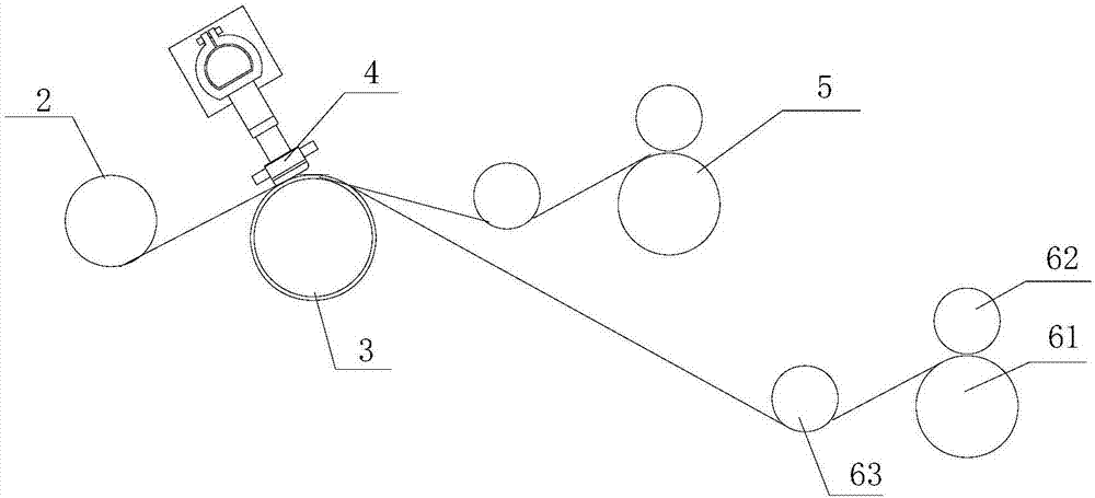
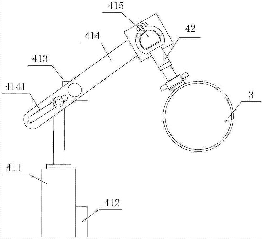
[0023] refer to Figure 1 to Figure 6 A cloth slitting device of the present invention comprises a frame 1, an adjustable guide roller mechanism 2, a slitting roller assembly 3, a slitting device 4, a first winding device 5 and a second winding device 6, the adjustable Both sides of guide roller mechanism 2 are provided with adjustment device 21, and guide roller assembly 22 is installed between described adjustment device 21, and several knife holders 31 are installed on described cutting roller assembly 3, and described cutting roller assembly 3 The top of the cutting device 4 is provided with a driving mechanism 41 on both sides of the cutting device 4. A mounting bracket 415 is installed between the driving mechanisms 41, and several cutter assemblies are installed on the mounting bracket 415. 42, the cutter assembly 42 cooperates with the knife seat 31, and the frame 1 is sequentially provided with a guide roller assembly 22, a slitting roller assembly 3, a first winding ...


PUM


Abstract

The invention provides a cloth cutting device. The cloth cutting device comprises a rack, an adjustable guide roller mechanism, a cutting roller component, a cutting device, a first rolling device and a second rolling device, wherein an adjusting device is arranged on each of two sides of the adjustable guide roller mechanism; a guide roller component is mounted between the adjusting devices; a plurality of tool aprons are mounted on the cutting roller component; the cutting device is arranged above the cutting roller component; a driving mechanism is arranged on each of two sides of the cutting device; a mounting support is mounted between the driving mechanisms; a plurality of cutter components are mounted on the mounting support; the guide roller component, the cutting roller component, the first rolling device and the second rolling device are sequentially arranged on the rack in the cloth moving direction; and a buffer spring is arranged on each cutter component. The pressure between hot cutters and cutter rests can be automatically adjusted, so that cutter abrasion is reduced, cloth is guaranteed by a compression roller component to be always clung to a wind-up roller component, and accordingly, even and no-fold winding is ensured.

Description

[0001] 【Technical field】 [0002] The invention relates to the technical field of cloth production, in particular to a cloth cutting device. [0003] 【Background technique】 [0004] In the textile industry, cloth slitting equipment is often used to divide the raw edge of the cloth or the cloth into small sections of equal or different lengths according to customer requirements for winding and packaging. However, the structure of the current slitting machine is unreasonable and requires multiple Workers manually press the cutting knife to divide, which increases the labor cost of the enterprise, and the current cutting knife has poor adaptability in the cutting process, requires manual fine-tuning, and causes serious wear to the cloth guide roller during the long-term cutting process After the production is completed, the fabric needs to be rolled. The rolled fabric is convenient for storage and transportation. In the textile industry, due to the consideration of the transportat...

Claims


Application Information

Patent Timeline
Patent Type & Authority Applications(China)
IPC IPC(8): B26D1/03B26D7/06B26D7/14B26D7/26B26D7/32B26D7/02B26D7/10D06H7/00
CPCD06H7/00B26D1/035B26D7/025B26D7/0625B26D7/10B26D7/14B26D7/2614B26D7/2628B26D7/32B26F2210/12B26D2007/322
Inventor 王建兵
Owner 杭州世佳布艺有限公司
Why Eureka
Try Eureka