Hazardous fluid pipe pressure-controlling temperature-reducing valve device

A technology for valve devices and fluid pipelines, which is applied in the direction of valve devices, valve operation/release devices, pipeline heating/cooling, etc., to achieve the effect of easy replacement

Active Publication Date: 2018-12-07
JIANGSU GAOTE VALVE IND CO LTD
View PDF6 Cites 4 Cited by
  • Summary
  • Abstract
  • Description
  • Claims
  • Application Information

AI Technical Summary

Problems solved by technology

[0003] In life, we often use valves to adjust the size of water flow, but at the same time, there are basically no va...

Method used


Image

  • Hazardous fluid pipe pressure-controlling temperature-reducing valve device
  • Hazardous fluid pipe pressure-controlling temperature-reducing valve device
  • Hazardous fluid pipe pressure-controlling temperature-reducing valve device

Examples


Embodiment Construction

[0034] The present invention is described in detail below in conjunction with accompanying drawing and specific embodiment:

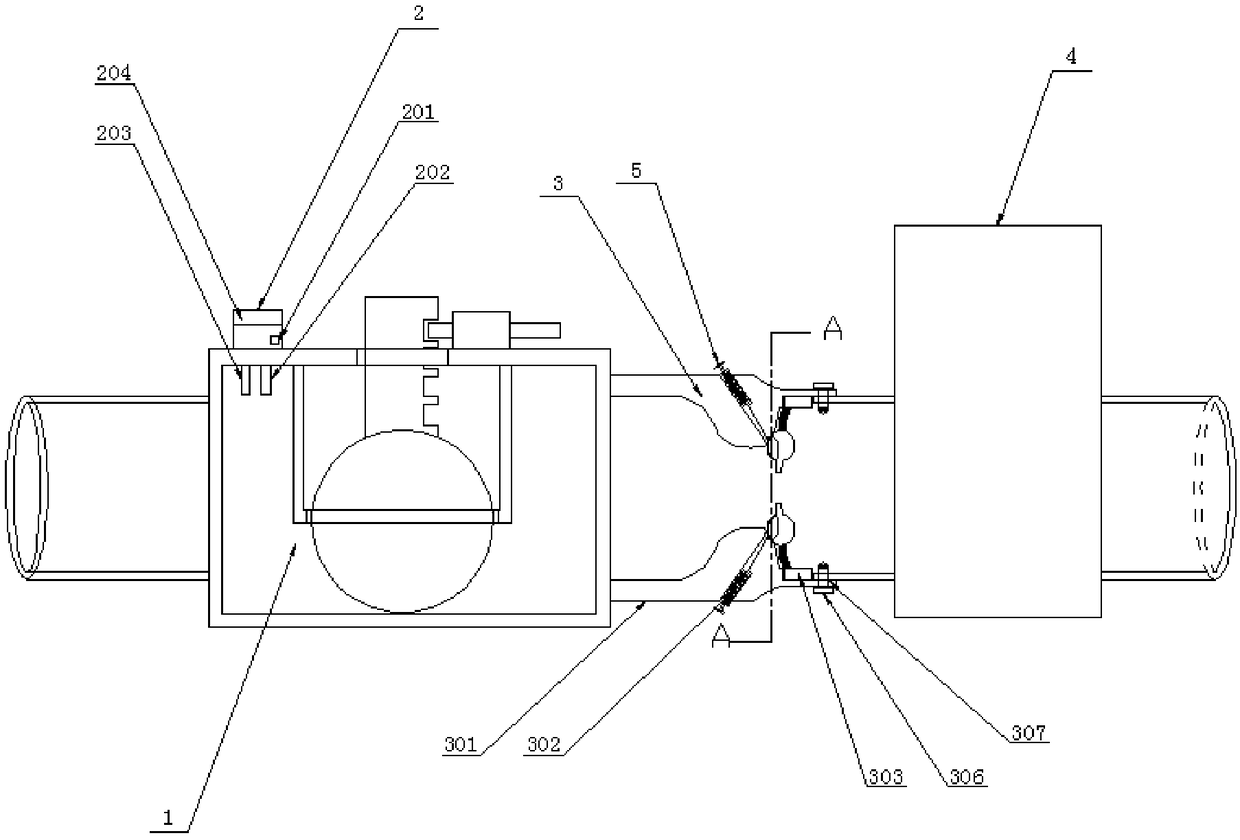
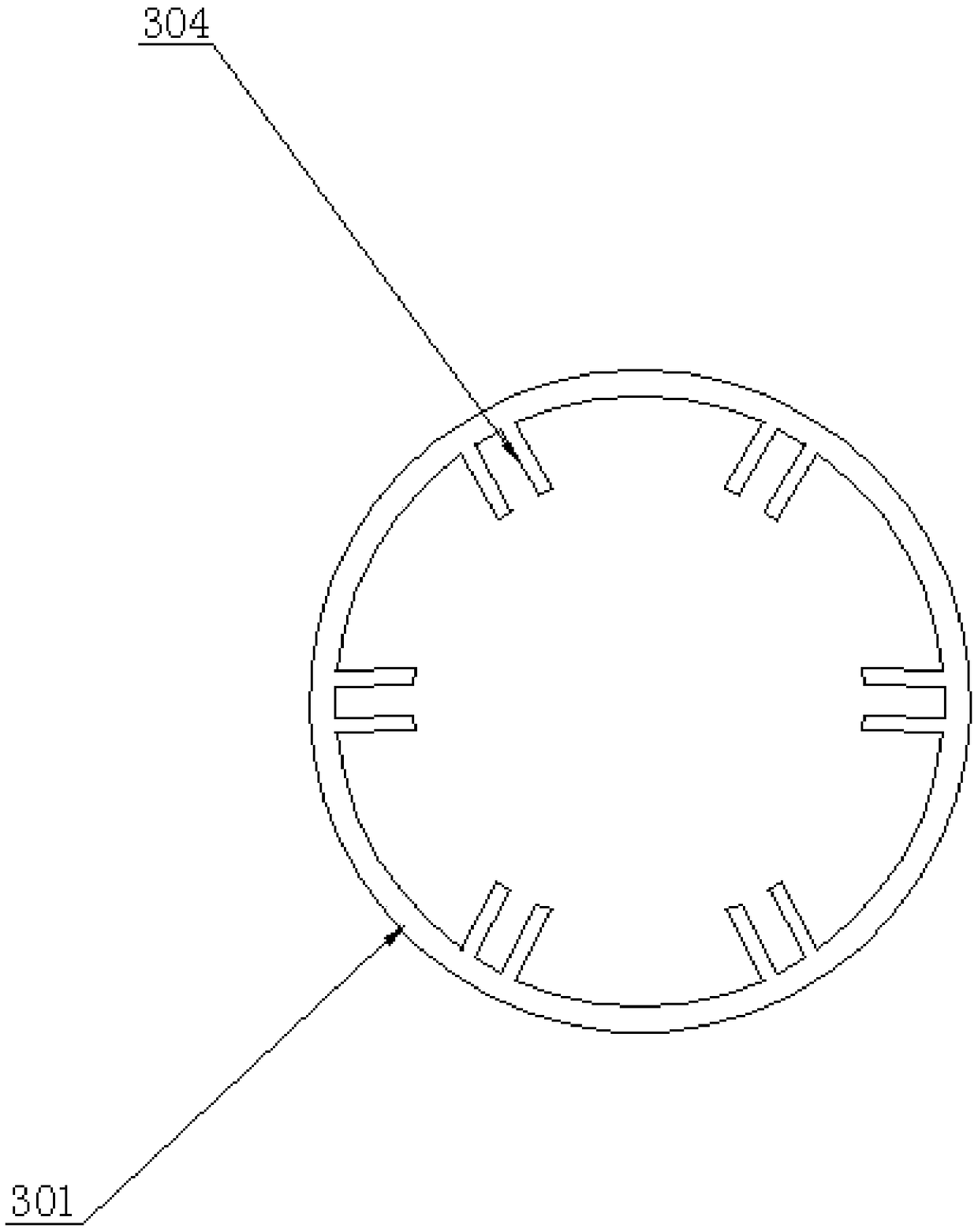
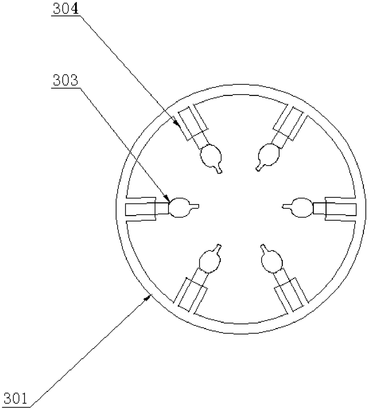
[0035] refer to Figure 1-8As shown, a valve device for controlling pressure and cooling of a toxic fluid pipeline includes a valve body 1, a sensor assembly 2, a pressure reducing device 3, a cooling device 4, and a return device 5. The sensor assembly 2 is arranged on the valve body 1, and the The pressure reducing device 3 is arranged at one end of the water outlet of the valve body 1, the cooling device 4 is arranged on the outlet pipe next to the pressure reducing device 3, and the return device 5 is arranged in the liquid outlet 302 of the pressure reducing device 3 The sensor assembly 2 includes a pressure sensor 202, a temperature sensor 203, a central processing unit 201 and a display screen 204, and the pressure sensor 202, the temperature sensor 203 and a display screen 204 are connected to the central processing unit 201, and the pressure re...


PUM


Abstract

The invention discloses a hazardous fluid pipe pressure-controlling temperature-reducing valve device which comprises a valve body, a sensor assembly, a pressure reducing device, a temperature reducing temperature and a reflowing device. The sensor assembly is arranged on the valve body; the pressure reducing device is arranged at one end of a water outlet of the valve body; the temperature reducing temperature is arranged on a water outlet pipe and close to the pressure reducing device; the reflowing device is arranged in a liquid outlet of the pressure reducing device; the pressure reducingdevice comprises a special-shaped wall, the liquid outlet, a pressure reducing body and a limiting groove; the reflowing device comprises a guide pillar; one end of the guide pillar and a plunger arefixedly connected into the liquid outlet; and the other end of the guide pillar penetrates through a guide sleeve on a sealed block and stretches out to the outer side of the liquid outlet so as to befixedly connected with a block body. According to the hazardous fluid pipe pressure-controlling temperature-reducing valve device provided by the invention, the pressure intensity can be automatically controlled, the fluid temperature is adjusted, the energy is saved, and the occurrence of the phenomenon that a hazardous and polluted fluid leaks to pollute the environment and affect the human body health can be effectively prevented.

Description

Technical field: [0001] The invention relates to the field of valves, in particular to a valve device for pressure control and temperature reduction of toxic fluid pipelines. Background technique: [0002] A valve is a control component in a fluid delivery system, with functions such as cut-off, regulation, flow diversion, reverse flow prevention, pressure stabilization, flow diversion, or overflow pressure relief. Valves used in fluid control systems range from the simplest cut-off valves to various valves used in extremely complex automatic control systems, with a wide variety of varieties and specifications. Valves can be used to control the flow of various types of fluids such as air, water, steam, various corrosive media, mud, oil, liquid metal and radioactive media. Valves are also divided into cast iron valves, cast steel valves, stainless steel valves (201, 304, 316, etc.), chrome-molybdenum steel valves, chrome-molybdenum-vanadium steel valves, duplex steel valves,...

Claims


Application Information

Patent Timeline
IPC IPC(8): F16K17/38F16K31/70F16K37/00F16L55/02F16L53/70
CPCF16K17/38F16K31/002F16K37/0091F16L53/70F16L55/02
Inventor 李友秀
Owner JIANGSU GAOTE VALVE IND CO LTD
Why Eureka
Try Eureka