Oil steam zero-discharge oil storage tank device

A technology of oil vapor and oil storage tanks, applied in packaging, transportation, packaging, containers, etc., can solve problems such as power consumption, and achieve the effect of eliminating fire hazards

Inactive Publication Date: 2011-06-29
程景池
View PDF8 Cites 5 Cited by
  • Summary
  • Abstract
  • Description
  • Claims
  • Application Information

AI Technical Summary

Problems solved by technology

However, the syst

Method used


Image

  • Oil steam zero-discharge oil storage tank device
  • Oil steam zero-discharge oil storage tank device
  • Oil steam zero-discharge oil storage tank device

Examples


Embodiment 1

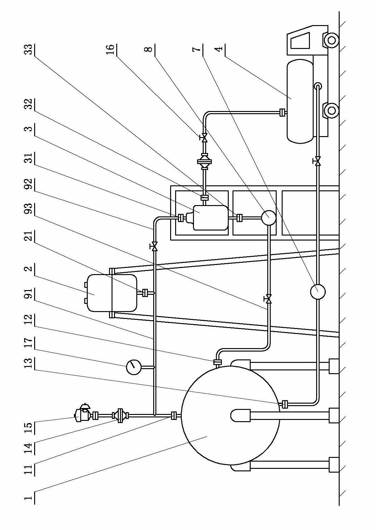
[0015] see figure 1 , figure 2 , the oil vapor zero-emission oil storage tank device of the present invention includes at least one oil storage tank 1, an oil vapor throughput interface 11 and a condensed oil recovery interface 12 are arranged on the upper part or the top of the oil storage tank, and the lower part or the bottom of the oil storage tank Set the liquid oil output interface 13; according to the needs of the design, the oil vapor throughput interface and the condensed oil recovery interface can be set on the upper part of the oil storage tank, and the liquid oil output interface can be set on the lower part of the oil storage tank; the oil vapor can also be set on the top of the oil storage tank The throughput interface and the condensed oil recovery interface, the liquid oil output interface is set at the bottom of the oil storage tank; the preferred solution is to set the oil vapor throughput interface on the top of the oil storage tank, the Set the liquid oil...

Embodiment 2

[0021] The oil storage tank device in this embodiment is an improvement on the basis of Embodiment 1. The technical content disclosed in Embodiment 1 will not be described repeatedly, and the content disclosed in Embodiment 1 also belongs to the content disclosed in this embodiment.

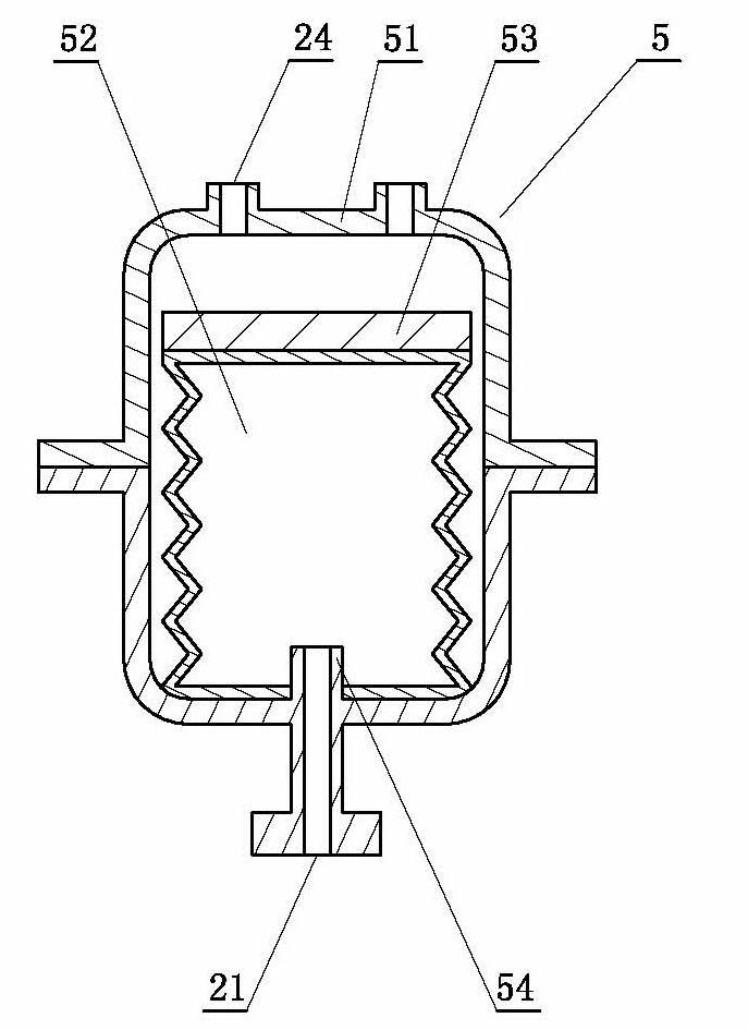
[0022] see image 3 ( image 3is a cross-sectional view), in this embodiment, the oil vapor intake and puff compensator 5 includes a protective cylinder 51, a bellows variable volume air chamber 52, and a counterweight 53, and the bellows variable volume air chamber is arranged on the protective cylinder Inside, the counterweight is arranged on the top of the bellows variable volume air chamber, the oil vapor breathing tube interface 21 is arranged outside the protective cylinder, and a breathing tube 54 is arranged on the bellows variable volume air chamber, The breathing tube communicates with the oil vapor breathing tube interface. The protective tank body is made of carbon steel, and a plur...

Embodiment 3

[0024] The oil storage tank device in this embodiment is an improvement on the basis of Embodiment 1. The technical content disclosed in Embodiment 1 will not be described repeatedly, and the content disclosed in Embodiment 1 also belongs to the content disclosed in this embodiment.

[0025] see Figure 4 ( Figure 4 is a sectional view), in this embodiment, the oil vapor huff and puff compensator 6 includes a water-sealed pool 61 and a floating bucket-type variable-volume air chamber 62, and the floating-bucket-type variable-volume air chamber is arranged in the water-sealed pool, The oil vapor breathing tube interface 21 is arranged outside the water-sealed pool, and a breathing tube 64 is arranged in the floating bucket type variable volume air chamber, and the breathing tube communicates with the oil vapor breathing tube interface. In this embodiment, the water-sealed pool and the floating bucket-type variable volume air chamber are made of engineering plastics, and the w...


PUM

PropertyMeasurementUnit
Volumeaaaaaaaaaa

Abstract

The invention relates to an oil steam zero-discharge oil storage tank device. The oil storage tank device comprises at least one oil storage tank; an oil steam huff-puff interface and a condensed oil recovery interface are arranged at the upper part or the top of the oil storage tank; a liquid oil exporting interface is arranged at the lower part or the bottom of the oil storage tank; an oil steam huff-puff compensator is arranged on one side of the oil storage tank; an oil steam breathing tube interface arranged on the oil steam huff-puff compensator is communicated with the oil steam huff-puff interface through an oil steam pipeline and communicated with a purified gas outlet of an oil gas separator through a purified gas pipeline; an oil steam importing interface is arranged at the central part of the oil gas separator; a condensed oil exporting interface arranged at the bottom of the oil gas separator is communicated with the condensed oil recovery interface through a condensed oil recovery pipeline; an oil delivery pump is arranged in the condensed oil recovery pipeline; and the volume of the oil steam huff-puff compensator is automatically adjusted according to the throughout of oil steam.

Description

technical field [0001] The invention relates to an oil vapor zero discharge oil storage tank device. The oil storage tank device is provided with an oil vapor throughput interface and a condensed oil recovery interface, and has an oil vapor throughput compensator. The oil vapor throughput compensator communicates with the oil vapor through an oil vapor pipeline. The oil vapor throughput interface is connected, and the volume of the oil vapor throughput compensator is automatically adjusted according to the oil vapor throughput. Background technique [0002] In the prior art, there is a breather valve on the oil storage tank. When the oil is output from the oil storage tank to the tank truck, the oil delivery pipe is connected to the oil port of the tank truck to load oil, and at the same time, the exhaust port on the tank truck is opened to eliminate The oil vapor generated in the tank truck; when the tank truck feeds oil into the oil storage tank, the upper breather valve o...

Claims


Application Information

Patent Timeline
IPC IPC(8): B65D90/30B65D90/32
Inventor 程景池
Owner 程景池
Why Eureka
Try Eureka