Novel exhaust system

An exhaust system, a new type of technology, applied in aerodynamic tests, measuring devices, instruments, etc., to achieve the effects of long continuous operation, stable airflow pressure in the flow field, and improved test efficiency

Inactive Publication Date: 2017-08-25
四川瑞晟石油设备开发有限公司
View PDF2 Cites 0 Cited by
  • Summary
  • Abstract
  • Description
  • Claims
  • Application Information

AI Technical Summary

Problems solved by technology

The system cannot be evacuated un

Method used


Image

  • Novel exhaust system
  • Novel exhaust system
  • Novel exhaust system

Examples


Embodiment Construction

[0022] The present invention will be further described below in conjunction with accompanying drawing, protection scope of the present invention is not limited to the following:

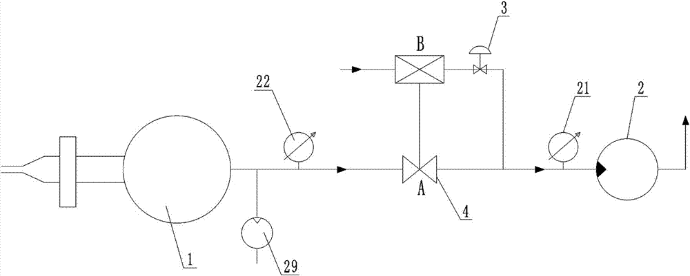
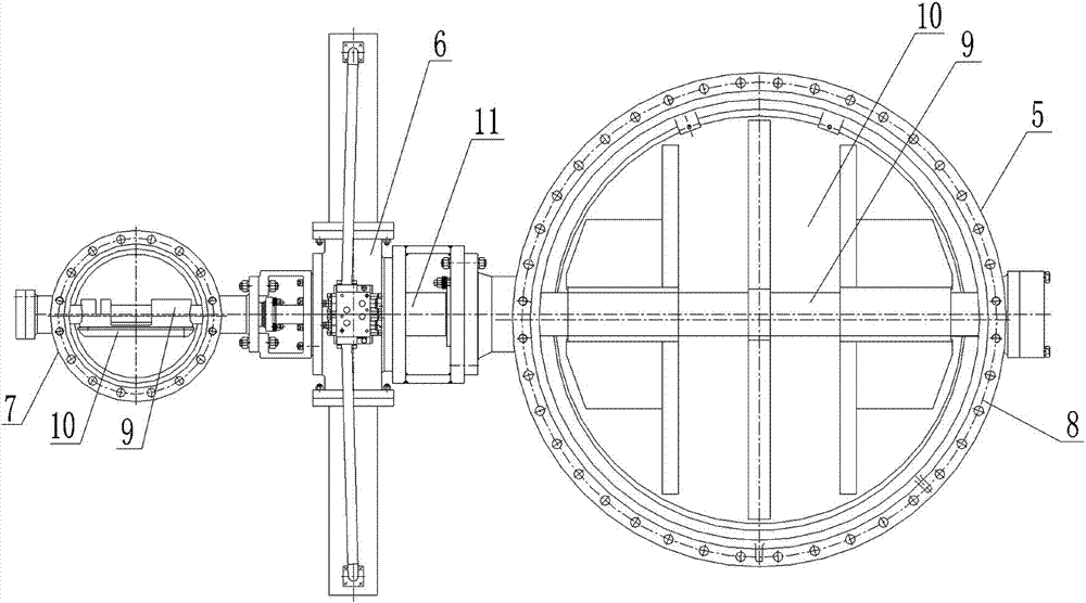
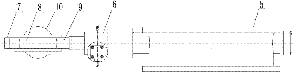
[0023] Such as Figure 1~3 As shown, a novel exhaust system includes a vacuum spherical tank 1, a centrifugal vacuum pump 2, a regulating valve 3 and a vacuum switching valve 4, and the vacuum switching valve 4 is located between the vacuum spherical tank 1 and the centrifugal vacuum pump 2; The vacuum switching valve 4 described above is composed of a valve A5, a motor 6 and a valve B7. The motor 6 is located between the valve A5 and the valve B7. Both the valve A5 and the valve B7 are composed of a valve body 8, a valve shaft 9 and a valve plate 10. The valve shaft 9 is installed vertically through the valve body 8 and the two ends of the valve shaft 9 rotate on both sides of the valve body 8, the valve plate 10 located in the valve body 8 is installed on the valve shaft 9, the valve body 8 of the ...


PUM


Abstract

The invention discloses a novel exhaust system, which includes a vacuum spherical tank (1), a centrifugal vacuum pump (2), a regulating valve (3) and a vacuum switching valve (4). The vacuum switching valve (4) is located in the vacuum spherical tank ( 1) and the centrifugal vacuum pump (2). The invention has the beneficial effects of long continuous operation time, stable airflow pressure in the flow field of the control wind tunnel test section, accurate repetition of air flow state parameters in a given test section, and improved wind tunnel operation test efficiency.

Description

technical field [0001] The invention relates to the technical field of a vacuum exhaust system for wind tunnel tests, in particular to a novel exhaust system. Background technique [0002] A wind tunnel is a pipeline-shaped experimental device that artificially generates and controls airflow to simulate the flow of air around an aircraft or object, and can measure the effect of airflow on an object and observe physical phenomena. It is the most commonly used and most effective for aerodynamic experiments. Tool of. The hypersonic wind tunnel can take into account the environment of supersonic flight and the time required for dynamic pressure to a large extent, and can simulate different combinations of total pressure parameters to meet the basic requirements of the flight environment of supersonic vehicles at different flight altitudes. The hypersonic wind tunnel is mainly composed of a gas source system, a combustion heater, a nozzle, a test section, a diffuser, a vacuum ba...

Claims


Application Information

Patent Timeline
IPC IPC(8): G01M9/04
CPCG01M9/04
Inventor 李渭刘猛黄帮权孙传林徐世江
Owner 四川瑞晟石油设备开发有限公司
Why Eureka
Try Eureka