
Close-loop simulation-based distributed load optimization design method for carrier

A technology of distributed load and closed-loop simulation, which is applied in computer-aided design, design optimization/simulation, instrumentation, etc., and can solve the problems of not being able to fully consider the impact, not covering all working conditions, and not being comprehensive enough

Active Publication Date: 2017-08-25
BEIJING INST OF ASTRONAUTICAL SYST ENG +1
View PDF2 Cites 6 Cited by
  • Summary
  • Abstract
  • Description
  • Claims
  • Application Information

AI Technical Summary

Problems solved by technology

First of all, due to the conservativeness of the swing angle provided by the static calculation, the corresponding open-loop load has a certain degree of conservatism in the two parts of the aerodynamic load and the control load; secondly, due to the limitation of the static calculation, the swing inertial force, The additional loads generated by the aerodynamic damping force, etc., cannot fully consider the influence of the addition of control on these two parts of the load in the calculation of the sway load and elastic load; again, the open-loop load calculation is carried out based on some artificially determined characteristic conditions However, it cannot cover all working conditions during rocket flight; the calculation process of sloshing load and elastic load is similar, and the swaying tail and elastic displacement are all based on experience, and the design margin is often large
[0003] Therefore, on the one hand, the open-loop load calculation is conservative to a certain extent, and on the other hand, it is not comprehensive enough. It is very necessary to carry out research on the optimization technology of the vehicle distribution load based on the closed-loop simulation of the full dynamics of the six degrees of freedom of the rocket, that is, the closed-loop load calculation.

Method used


Image

  • Close-loop simulation-based distributed load optimization design method for carrier
  • Close-loop simulation-based distributed load optimization design method for carrier
  • Close-loop simulation-based distributed load optimization design method for carrier

Examples


Embodiment Construction

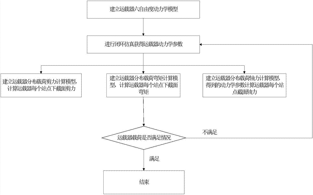
[0050] like figure 1 Shown, the steps of the present invention are as follows:

[0051] (1) Establish a six-degree-of-freedom dynamic model for the vehicle.

[0052] The establishment process is as follows:

[0053] First, establish the center-of-mass dynamic equation as follows:

[0054]

[0055]

[0056] is the apparent acceleration of the vehicle coordinate system

[0057] is the transformation matrix from the launch system to the launch system

[0058] V=L T (A 0 ,B 0 ,ω e ,t)V a -ω e ×r

[0059]

[0060] In the formula:

[0061] Acceleration of the center of mass of the vehicle in the launching inertial system; x a ,y a ,z a : The position of the center of mass of the vehicle in the launch inertial coordinate system

[0062] Velocity of the vehicle's center of mass relative to the launch inertial frame.

[0063] is the transformation matrix between the rocket body coordinate system and the launching inertial system; γ, ψ, are the roll a...


PUM


Abstract

The invention discloses a close-loop simulation-based distributed load optimization design method for a carrier. The method comprises the steps of firstly building a six-degree-of-freedom dynamics model for the carrier, then performing close-loop simulation to obtain dynamics parameters, building a distributed load shear force calculation model, a bending moment calculation model and an axial force calculation model of the carrier, and calculating lower section shear force, lower section bending moment and section axial force of each site of the carrier; and secondly, rechecking the situation on whether loads of the carrier meet the requirements or not, if the loads of the carrier meet the requirements, ending the design, if the loads of the carrier do not meet the requirements, optimizing a close-loop simulation input, re-obtaining the dynamics parameters, and calculating the lower section shear force, the lower section bending moment and the section axial force of each site, until the loads of the carrier meet the requirements. According to the method, the loads on all the sections of the carrier of a rocket in a flight process can be really reflected; and therefore, the method is of great significance for rechecking the completeness and design margin of load design.

Description

technical field [0001] The invention relates to a closed-loop simulation-based optimized design method for distributed load of a carrier, belonging to the field of overall design of the carrier. Background technique [0002] The traditional distribution load calculation of the vehicle includes: aerodynamic load, maneuvering load, swaying load and elastic load, among which the aerodynamic load and maneuvering load are calculated by the load professional based on the static calculation results of the attack and swing angle provided by the attitude control professional. The interaction of various parameters between control systems is not considered, which can be called open-loop load calculation. First of all, due to the conservativeness of the swing angle provided by the static calculation, the corresponding open-loop load has a certain degree of conservatism in the two parts of the aerodynamic load and the control load; secondly, due to the limitation of the static calculatio...

Claims


Application Information

Patent Timeline
IPC IPC(8): G06F17/50
CPCG06F30/17G06F30/20G06F2111/10G06F2119/06
Inventor 程兴李君陈宇余光学杨云飞汤波张普卓邓舞燕陈彬陈海鹏杨树涛胡鹏翔张欢
Owner BEIJING INST OF ASTRONAUTICAL SYST ENG
Learn More