Load-optimized interior of a piston

a technology of interior and load, applied in the direction of trunk pistons, machines/engines, plungers, etc., can solve the problem of not providing adequate component stiffness for more highly stressed pistons

Inactive Publication Date: 2010-04-29
KOLBENSCHMIDT AG
View PDF9 Cites 14 Cited by
  • Summary
  • Abstract
  • Description
  • Claims
  • Application Information

AI Technical Summary

Benefits of technology

[0004]In accordance with the invention, the piston interior encompasses, to the extent possible ribs, aligned in the direction of the boss holes, the ribs being connected in one piece to the boss base body or the piston crown and creating a continuous connection between the pin bosses. The ribs effectively stiffening th...

Problems solved by technology

It has been shown that stiffening ribs with proximately uniform wall thickness disposed...

Method used


Image

  • Load-optimized interior of a piston
  • Load-optimized interior of a piston
  • Load-optimized interior of a piston

Examples


Embodiment Construction

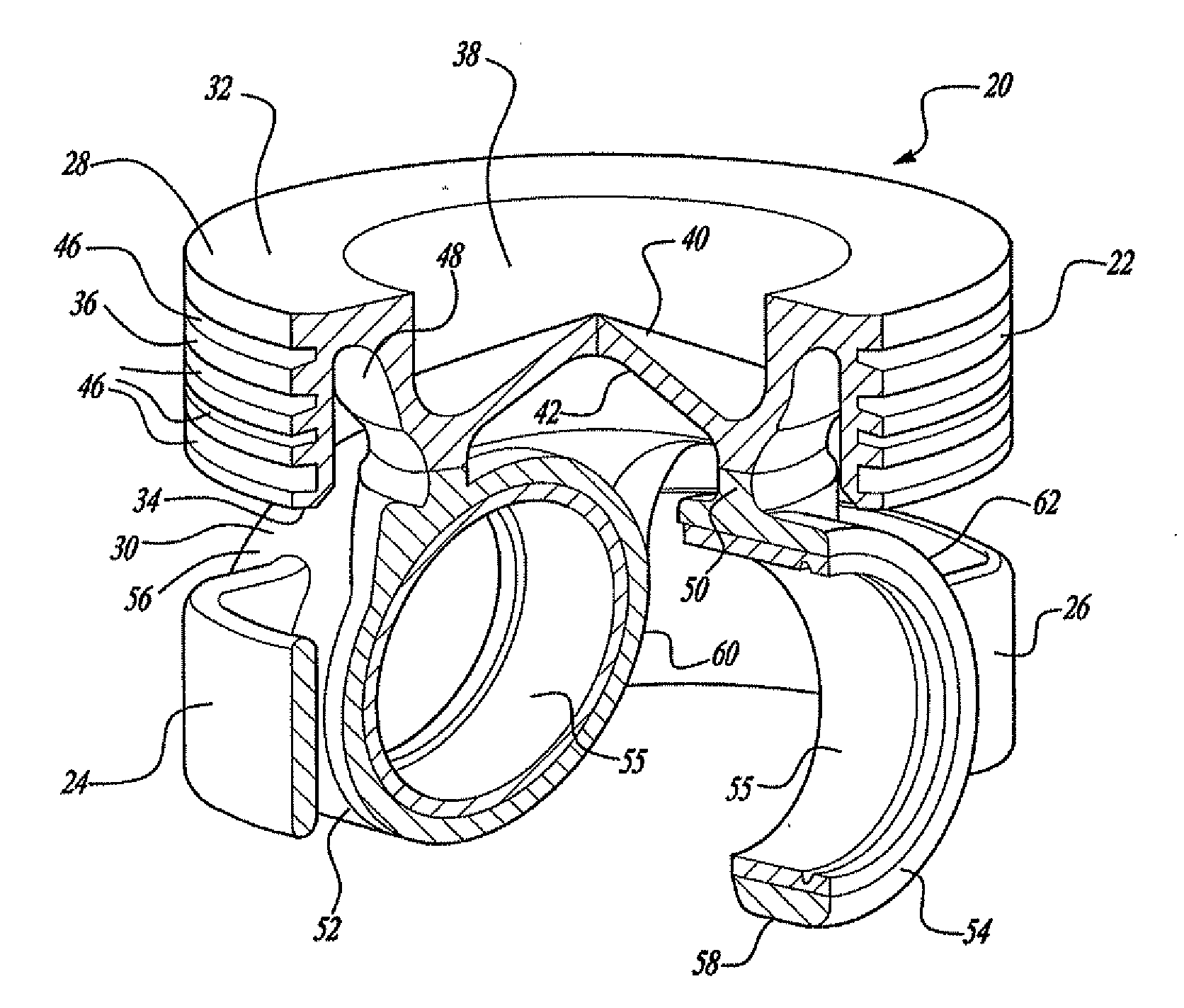
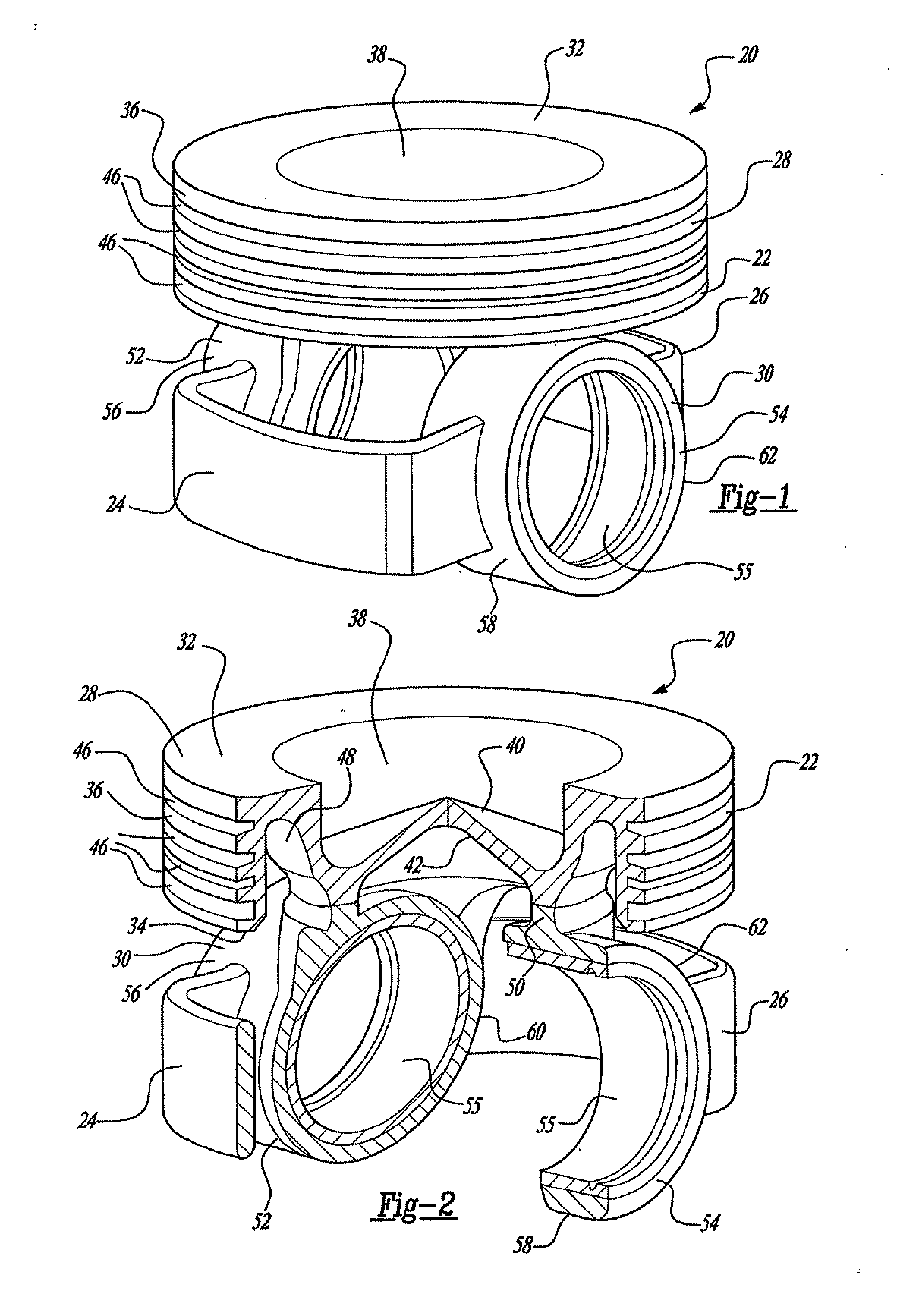
[0019]The piston 1 shown in FIG. 1 is fashioned as a cooling-channel piston that comprises a piston crown 2 as a piston upper part and a piston skirt 3 as a piston lower part, where these components are supported by connecting webs 4a, 4b. In order to create one structural unit, at least the connecting webs 4a, 4b are friction welded and a material joint is created thereby, where the connecting webs 4a, 4b from weld beads 5a, 5b on both sides. The piston crown 2 has a combustion bowl 6 on its face and a top land 7 on its exterior adjoining a ring zone 8 to locate piston rings (not shown). Spaced apart from the ring 8, a first radially circumferential cooling channel 9 and a central cooling channel 10 are integrated in the piston 1 that, in the operating state, are contacted in common by a cooling medium. The piston skirt 3 immediately adjoining the right zone 4 encompasses two diametrically opposed skirt wall sections 11, and offset thereto, two pin bosses 12 with integral boss hole...


PUM


Abstract

A piston of an internal combustion engine has a piston crown provided with a ring zone and adjoining a piston skirt encompassing a piston interior, the skirt having two load-bearing skirt wall segments and two pin bosses. Each pin boss encompassing a boss hole is connected to a boss base body by a boss support, the base body having ribs to increase stiffness, which are aligned to the extent possible in the direction of the boss holes continuously connecting the pin bosses. The curved or arched ribs thereby cover a pivoting range of a connecting rod.

Description

BACKGROUND[0001]The invention relates to a piston of an internal combustion engine having a piston crown provided with a ring zone and adjoining a piston skirt that forms two diametrically opposed load-bearing piston skirt sections and two pin bosses offset thereto that together encompass a piston interior.[0002]Internal combustion engines that are more highly stressed, with increased specific outputs and reduced fuel consumption, require low reciprocating masses and therefore optimized pistons, without limiting their service life. It is known to provide such pistons with stiffening ribs in order to achieve sufficient durability. The stiffening ribs intended to achieve increased component strength are preferably designed with uniform dimensions. The known ribs are disposed in the piston interior spaced apart from the circumferential surface of the piston skirt and thus rotationally symmetrical to a vertical axis of the piston. It has been shown that stiffening ribs with proximately ...

Claims


Application Information

Patent Timeline
IPC IPC(8): F02F3/00F16J1/14
CPCF02F3/003F02F2003/0061F02F3/0076
Inventor GNIESMER, VOLKER
Owner KOLBENSCHMIDT AG
Why Eureka
Try Eureka