
Air brake valve for passenger train

An air brake valve, railway passenger car technology, applied in the direction of brakes, brake components, control valves and air release valves, etc., can solve problems such as non-stop exhaust air, alleviate problems, etc., and achieve the effect of stable operation and simple structure

Active Publication Date: 2017-08-29
CHINA RAILWAYS CORPORATION +2
View PDF18 Cites 12 Cited by
  • Summary
  • Abstract
  • Description
  • Claims
  • Application Information

AI Technical Summary

Problems solved by technology

Some problems in use: natural relief, continuous exhaust, poor relief

Method used


Image

  • Air brake valve for passenger train

Examples


Embodiment Construction

[0013] Below in conjunction with accompanying drawing, the present invention is described in detail.

[0014] In order to make the object, technical solution and advantages of the present invention clearer, the present invention will be further described in detail below in conjunction with the accompanying drawings and embodiments. It should be understood that the specific embodiments described here are only used to explain the present invention, not to limit the present invention.

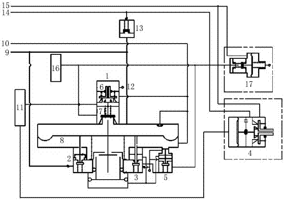
[0015] Such as figure 1 As shown, an air brake valve for a railway passenger car includes an action part 1, a working air cylinder charging valve 2, a balance valve 3, a balance valve 4 and a partial reduction closing valve 5, and the action part 1 includes an air supply valve 6, a stabilizing 7 and the main piston assembly 8, the upper chamber of the main piston assembly 8 of the action part 1 communicates with the train pipe 9 through the pipeline, and the lower chamber communicates with the wo...


PUM


Abstract

The invention discloses an air brake valve for a passenger train. The brake valve comprises an acting portion, an operating air cylinder charging valve, a counterbalance valve, a balance valve and a local reduction shutoff valve. The acting portion comprises an air supply valve, a stabilizing portion and a main piston assembly. Actions of the brake valve are controlled through pressure differences caused by train pipe pressure variation so as to realize functions of charging, braking, pressure retaining, relieving and the like; the pressure of a braking cylinder is controlled by the pressure of a volume chamber, and two-pressure indirect control of the air brake valve of the passenger train is realized; by replacement of a traditional slide valve structure with a diaphragm plate and check valve plunger structure, structural simplicity and stability and reliability in operation are realized.

Description

technical field [0001] The invention mainly relates to an air brake valve for a railway passenger car. Background technique [0002] The railway passenger car air brake valve is the core component of the railway passenger car braking system, which controls the inflation, braking and release of the railway passenger car. [0003] The brake valves used in passenger cars are mainly 104 type passenger car air distribution valve (hereinafter referred to as 104 valve) and F8 type passenger car air distribution valve (hereinafter referred to as F8 valve); the main control mechanism of 104 valve is a two-pressure slide valve structure; The control mechanism is a three-pressure plunger structure, which has the switchability of stage relief and one-time relief. When the conversion cover of the distribution valve is placed in the stage relief position, it can be programmed for special use. When the conversion cover of the distribution valve is placed in the first relief When in place,...

Claims


Application Information

Patent Timeline
Patent Type & Authority Applications(China)
IPC IPC(8): B60T15/02
CPCB60T15/021
Inventor 田宇吕超朱迎春安鸿肖维远谢磊刘保华宁波袁德强张杰
Owner CHINA RAILWAYS CORPORATION
Learn More