Heat storage type heating separating device

A heat storage device and separation device technology, which is applied in indirect heating carbonization, coking oven with horizontal carbonization chamber, petroleum industry, etc., can solve the problems of poor carbonization effect and poor gas purity, so as to improve the effect and avoid bias flow Effect

Inactive Publication Date: 2017-08-29
王萍
View PDF0 Cites 1 Cited by
  • Summary
  • Abstract
  • Description
  • Claims
  • Application Information

AI Technical Summary

Problems solved by technology

[0009] The purpose of the present invention is to provide a regenerative heating separation device, which has the characteristics of safety, high efficiency, good qua

Method used


Image

  • Heat storage type heating separating device
  • Heat storage type heating separating device
  • Heat storage type heating separating device

Examples


Embodiment 1

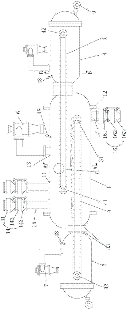
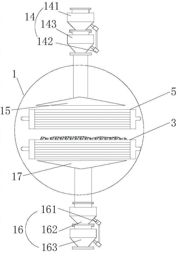
[0065] Such as figure 1 As shown, the present invention provides a regenerative heating separation device, which has the characteristics of good dry distillation effect, good dry distillation gas phase quality, and high dry distillation efficiency, comprising a dry distillation device 1, a first heating device 2, a first heat storage device 3 and The first driving device, the carbonization device 1 is a hollow structure, and a carbonization chamber for carbonizing materials is arranged inside. The top of the carbonization device 1 is provided with at least one feed port 11 and a gas outlet 13, and the lower part of the carbonization device 1 is provided with a discharge port 12. ; The dry distillation device 1 is used for dry distillation of the materials placed therein;

[0066]In the present invention, the first heating device 2 is arranged on the left side of the carbonization device 1, and the first heating device 2 is used to heat and store the first heat storage device 3...

Embodiment 2

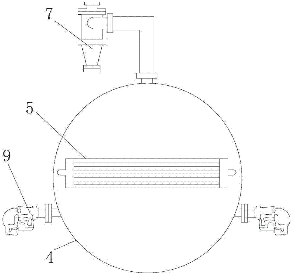
[0075] Such as figure 1 As shown, the difference between Embodiment 2 and Embodiment 1 is that the regenerative heating separation device also includes a second heating device 4, a second heat storage device 5 and a second driving device, and the second heating device 4 is arranged in the dry distillation device 1 On the right side, the second heat storage device 5 is a closed ring structure, one end of the second heat storage device 5 is located in the second heating device 4, the other end of the second heat storage device 5 is located in the carbonization device 1, and the first heat storage device 3 The ends of the second heat storage device 5 located in the carbonization device 1 are located at opposite ends, and the second drive device is connected to the second heat storage device 5 to drive the second heat storage device 5 clockwise or Rotating counterclockwise, a combined sealing device 33 is provided between the second heating device 4 and the carbonization device 1 ...


PUM


Abstract

The invention provides a heat storage type heating separating device, and relates to the technical field of dry distillation equipment. The heat storage type heating separating device comprises a dry distillation device, a first heating device, a first heat storage device and a first driving device. Feed inlets, a discharge outlet and a gas outlet are formed in the dry distillation device; the first heating device is positioned on a side of the dry distillation device; the first heat storage device is of a closed ring structure, one end of the first heat storage device is positioned in the first heating device, the other end of the first heat storage device is positioned in the dry distillation device, the first driving device is used for driving the first heat storage device to carry out circulating rotation, and a combined sealing device is arranged between the first heating device and the first heat storage device; the feed inlets are formed in the left end of the top of the dry distillation device and are particularly formed in positions above the first heat storage device; the discharge outlet is formed in the end, which is far away from the feed inlets, of the bottom of the dry distillation device and is particularly formed in the rear of the first heat storage device. Compared with the prior art, the heat storage type heating separating device has the advantages that the heat storage type heating separating device is safe and stabile in running, simple in structure and high in dry distillation efficiency, and obtained dry distillation gas phases are good in quality.

Description

technical field [0001] The invention relates to the technical field of dry distillation equipment, in particular to a heat storage type heating separation device which realizes gas-solid separation by heating materials through heat storage elements. Background technique [0002] Dry distillation is a reaction process in which solid or organic matter is heated and decomposed in the absence of air. As a result of dry distillation, various gases, vapors, and solids are formed. The mixture of gas and vapor is separated into gas and liquid after cooling. Dry distillation is a production process that humans have been familiar with and adopted for a long time, such as dry distillation of wood to make charcoal, and at the same time to obtain wood essence (methanol), wood acetic acid, etc. Before the First World War, acetone was industrially produced by neutralizing wood acetic acid obtained from wood dry distillation with lime, and then dry distillation. [0003] The dry distilla...

Claims


Application Information

Patent Timeline
IPC IPC(8): C10B5/10C10B47/40
CPCC10B5/10C10B47/40
Inventor 王平
Owner 王萍
Why Eureka
Try Eureka