

Spring adjusting device and valve assembly
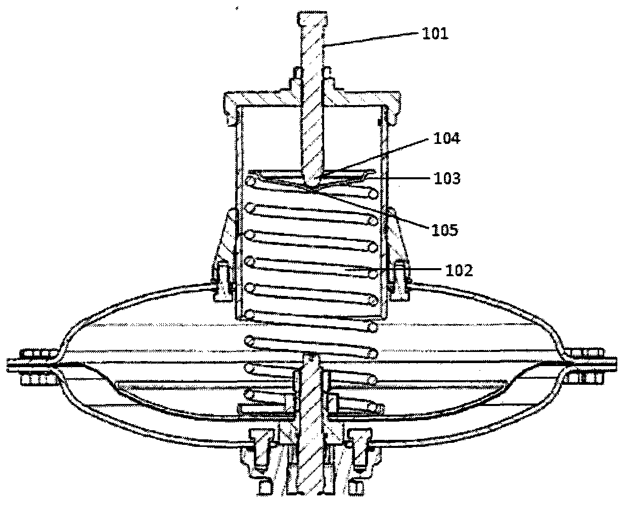
A technology of spring adjustment and spring seat, which is applied in the direction of valve devices, safety valves, balance valves, etc., can solve the problems of set point drift of valve assembly parameters, influence of spring use, spring 102 bending, etc., to improve work performance and enhance Effect of use, effect of preventing bending
- Summary
- Abstract
- Description
- Claims
- Application Information
AI Technical Summary
Problems solved by technology
Method used
Image

Examples
Embodiment 1
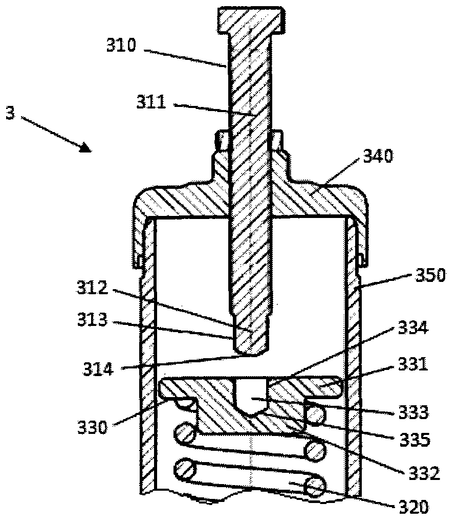
[0028] Such as image 3 As shown, the first embodiment of the present invention provides a valve assembly 3 . The valve assembly 3 includes a spring adjusting device, and the spring adjusting device mainly includes an adjusting screw 310 , a spring 320 and a spring seat 330 between the adjusting screw 310 and the spring 320 . The valve assembly 3 further includes a spring cover 340 and a spring cover 350 , an inner cavity formed by the two is used to accommodate one end of the adjusting screw 310 , the spring 320 and the spring seat 330 . A groove 333 having a cylindrical sidewall 334 is disposed on the spring seat 330 . Preferably, the spring seat 330 may be designed to include a top 331 and a bottom 332 extending downward from the top 331 . The top 331 blocks on the spring 320 , and the bottom 332 having a smaller outer diameter than the top 331 is engaged in the inner cavity of the spring 320 . The center of the top 331 is provided with a groove 333 with a cylindrical si...
Embodiment 2
[0033] Since the end portion is in direct contact with the spring seat, friction will occur with the spring seat when the adjusting screw is rotated, and the spring seat receives torsion force and transmits it to the spring, affecting the spring's use. Therefore, the second embodiment of the present invention provides a valve assembly with bearings, the following in conjunction with the attached Figure 5 And attached Image 6 The second embodiment of the present invention will be further described.
[0034] Such as Figure 5As shown, the second embodiment of the present invention provides a valve assembly 5 . The spring seat 530 is located on the upper end of the spring 520 . The bottom 532 of the spring seat is accommodated in the spring 520 , and the top 531 is located on the spring 520 . The end portion 512 is received in the groove 533 . The shape of the sidewall of the end portion 512 is determined according to the size of the sidewall of the groove 533 so that the...
Embodiment 3
[0039] Such as Figure 7 As shown, the third embodiment of the present invention provides a valve assembly 7 . The valve assembly 7 includes a spring seat 730 with a groove 733 and an adjusting screw 710 with a head portion 712 . The groove bottom 735 of the groove 733 is flat, and the end surface 714 of the end portion 712 is spherical. When the end portion 712 is accommodated in the groove 733 , the end surface 714 is in point contact with the groove bottom 735 . Due to the small contact area, the frictional force between the end surface 714 of the end portion 712 and the groove bottom 735 of the groove is reduced, thereby reducing the torsional force of the adjusting screw 710 on the spring, which is not easily damaged components. Other structures of the valve assembly 7 are similar to those of the valve assembly 3 provided in the first embodiment, and thus will not be repeated here.
PUM
 Abstract
Description
Claims
Application Information