A kind of piston suitable for circular pendulum reciprocating motion

A technology of reciprocating motion and piston, which is applied in the direction of machines/engines, pump components, liquid displacement machinery, etc., can solve problems such as limiting the working efficiency of compressors and affecting the shock absorption effect of air springs, and achieves good air tightness and improved The effect of work efficiency

Active Publication Date: 2019-06-11
枣庄明越科技咨询服务有限公司
View PDF7 Cites 0 Cited by
  • Summary
  • Abstract
  • Description
  • Claims
  • Application Information

AI Technical Summary

Problems solved by technology

[0004] And when using the traditional horizontal or vertical reciprocating compression method, often a single power device can only control one piston for compression, which limits the working efficiency of the compressor to a certain extent, and will affect the shock absorption effect of the air spring

Method used


Image

  • A kind of piston suitable for circular pendulum reciprocating motion
  • A kind of piston suitable for circular pendulum reciprocating motion
  • A kind of piston suitable for circular pendulum reciprocating motion

Examples


Embodiment 1

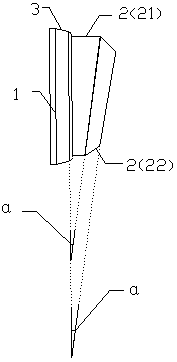
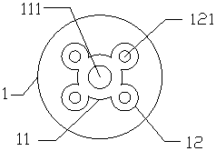
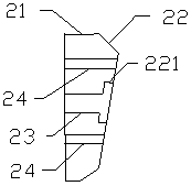
[0024] A piston suitable for reciprocating motion of a circular pendulum, such as Figure 1~3 As shown, it includes a piston head 1, a piston skirt 2 and a piston ring 3. The piston head 1 is mechanically connected to the piston skirt 2. Specifically, the bolt passes through the second bolt through hole inside the second spherical groove 12 provided. 121 is connected with the threaded through hole 24, and the piston head 1 is mechanically connected with the piston skirt 2. At this time, the first bolt through hole 111 inside the first spherical groove 12 is connected with the third bolt through hole 23, and the piston ring 3 Wrapping the gap outside the piston head 1 and mechanically connecting the piston head 1 and the piston skirt 2 , the piston skirt 2 includes a connecting section 21 at the front end and a working section 22 at the rear end.

[0025] In the above, in order to make the piston fully fit in the circular cylinder, the working section 22 and the connecting sect...

Embodiment 2

[0033] This embodiment is a specific improvement of Embodiment 1. According to the diameter of the annular cylinder of the air compressor and the size of its internal piston assembly, the included angle α is jointly determined to be 10°. During the specific working process, the piston can be in the annular cylinder and the inner wall Under the condition of complete fit, the circular pendulum motion is performed. During the circular pendulum motion, the piston ring 3 itself has a lubricating function, so the air compressor using the piston in this embodiment is an oil-free lubricating air compressor.

Embodiment 3

[0035] This embodiment is a specific improvement of Embodiment 1. According to the diameter of the annular cylinder of the air compressor and the size of its internal piston assembly, the included angle α is jointly determined to be 13°. During the specific working process, the piston can be in the annular cylinder and the inner wall Under the condition of complete fit, the circular pendulum motion is performed. During the circular pendulum motion, the piston ring 3 itself has a lubricating function, so the air compressor using the piston in this embodiment is an oil-free lubricating air compressor.


PUM


Abstract

The invention discloses a piston applicable to circumferential swinging reciprocating motion. The piston comprises a piston head, a piston skirt and a piston ring, wherein the piston head is mechanically connected with the piston skirt; concretely, a bolt penetrates through a second bolt through hole in a second spherical groove so as to be connected with a threaded through hole, so that the head part and the piston skirt are mechanically connected; at the time, a first bolt through hole in a first spherical groove communicates with a third bolt through hole; the piston ring covers the outer part of the piston head and covers a clearance of mechanical connection of the piston head and the piston skirt; and the piston skirt comprises a connecting section at the front end and a working section at the rear end. According to the piston provided by the invention, a traditional piston reciprocating motion manner is abandoned, the piston circumferentially swings like a pendulum during a compression process, in addition, lubricating oil has no need to be added during the compression process, and the compression efficiency is high.

Description

technical field [0001] The invention relates to the air compressor manufacturing field, in particular to a piston suitable for circular pendulum reciprocating motion. Background technique [0002] The air compressor is an important part of the air spring automobile shock absorption process. The air compressor compresses the air through the reciprocating movement of the piston assembly in the cylinder. The traditional air compressor uses the piston to make horizontal or vertical movements in the cylinder. Reciprocating motion realizes the compression of gas. [0003] Existing air compressors generally need to add lubricating oil between the piston and the inner wall of the cylinder when performing air compression, so as to reduce the frictional resistance between the piston and the cylinder and prolong the service life of the piston. [0004] And when using the traditional horizontal or vertical reciprocating compression method, often a single power device can only control o...

Claims


Application Information

Patent Timeline
Patent Type & Authority Patents(China)
IPC IPC(8): F04B39/00F04B39/02
CPCF04B39/0005F04B39/0292
Inventor 兰志强金国贤
Owner 枣庄明越科技咨询服务有限公司
Why Eureka
Try Eureka