Engine cooling water pump capable of preventing cooling liquid from being mixed into lubricating oil

A technology of engine cooling and lubricating oil, which is applied in the direction of liquid fuel engines, machines/engines, and parts of pumping devices for elastic fluids, etc. It can solve the problems of reducing the service life of water pumps, roughness, and entering lubricating oil chambers, etc. To achieve the effect of preventing risks

Active Publication Date: 2017-08-29
HUNAN OIL PUMP
View PDF5 Cites 2 Cited by
  • Summary
  • Abstract
  • Description
  • Claims
  • Application Information

AI Technical Summary

Problems solved by technology

[0002] For oil-lubricated engine cooling water pumps, oil seals and water seals need to be installed between the shaft and the pump body to isolate the coolant from the lubricating transmission system. Mixing into lubricating oil will lead to deterioration of lubricating oil quality, corrosion and erosion of metal parts, resulting in abnormal wear and tear, thereby reducing the service life of the water pump
In principle, no water can be mixed into the lubricating oil, but since the water seal cannot be completely sealed (generally the water seal will stipulate a minimum allowable leakage value), a small amount of water vapor evaporated

Method used


Image

  • Engine cooling water pump capable of preventing cooling liquid from being mixed into lubricating oil
  • Engine cooling water pump capable of preventing cooling liquid from being mixed into lubricating oil
  • Engine cooling water pump capable of preventing cooling liquid from being mixed into lubricating oil

Examples


Embodiment Construction

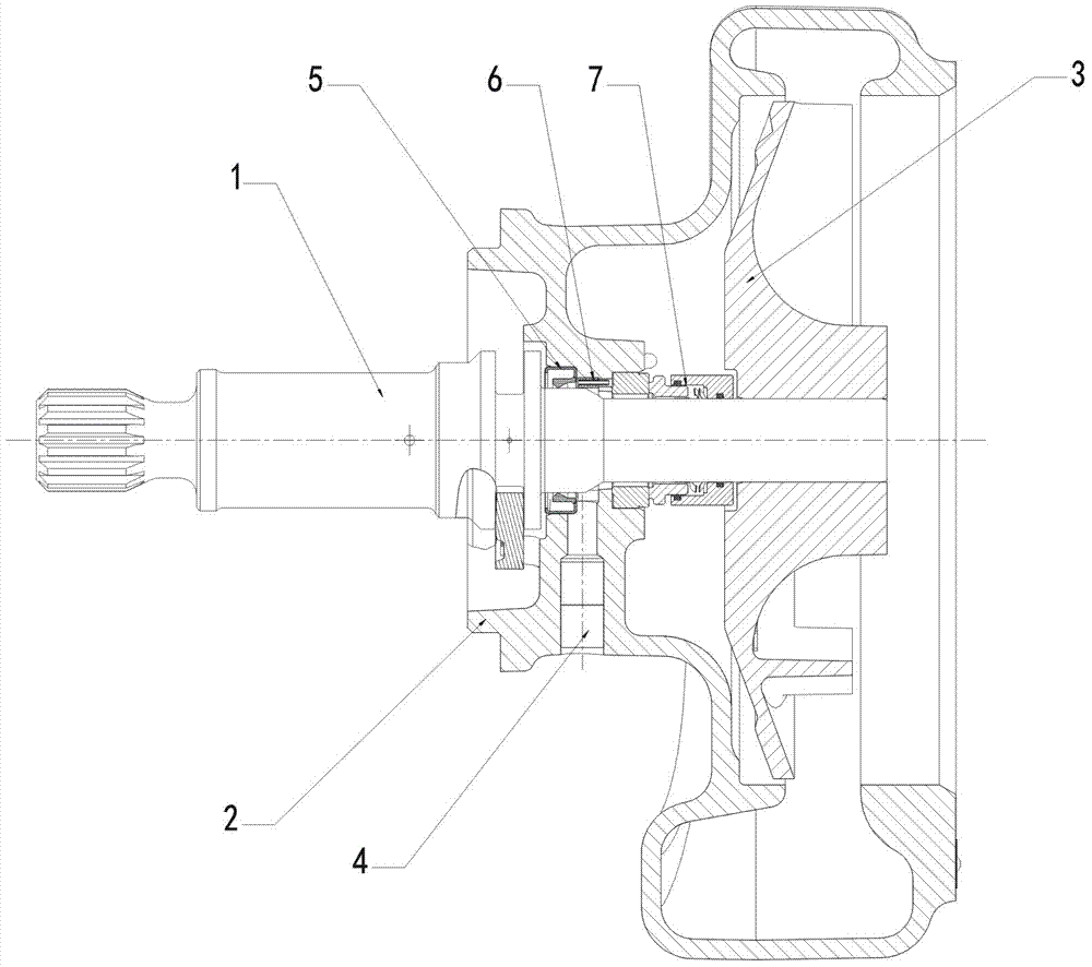
[0018] In order to facilitate the understanding of those skilled in the art, the present invention will be further described below in conjunction with the embodiments and accompanying drawings, and the contents mentioned in the embodiments are not intended to limit the present invention.

[0019] In describing the present invention, it should be understood that the terms "center", "longitudinal", "transverse", "length", "width", "thickness", "upper", "lower", "front", " Back", "Left", "Right", "Vertical", "Horizontal", "Top", "Bottom", "Inner", "Outer", "Clockwise", "Counterclockwise", etc. or The positional relationship is based on the orientation or positional relationship shown in the drawings, which is only for the convenience of describing the present invention and simplifying the description, rather than indicating or implying that the referred device or element must have a specific orientation, be constructed and operated in a specific orientation, Therefore, it should ...


PUM


Abstract

The invention provides an engine cooling water pump capable of preventing cooling liquid from being mixed into lubricating oil. The engine cooling water pump capable of preventing the cooling liquid from being mixed into the lubricating oil comprises a rotary shaft, a pump body and an impeller; a shaft hole and a drain hole are formed in the pump body, wherein the shaft hole is a stepped hole, and the drain hole communicates with the middle of the shaft hole; the impeller is mounted at the end of the rotary shaft; the rotary shaft is penetrated in the shaft hole of the pump body; and an oil seal and a water seal are arranged between the rotary shaft and the pump body in a sleeved mode, a deflector ring is arranged between the oil seal and the water seal, a notch is formed in the deflector ring, the position of the notch is aligned with the drain hole of the pump body, and the deflector ring is made of a material resistant to corrosion and high temperature and not prone to adhesion. According to the structure, on the one hand, water vapor leaking out of the water seal can be blocked to a certain extent and is prevented from directly making contact with the oil seal, and accordingly, the effect of supplementary seal can be achieved; on the other hand, condensed water drops can be guided into the drain hole and discharged in time through the notch of the flow guide ring, and the risk caused by water entering the lubricating system can be prevented.

Description

technical field [0001] The invention relates to an engine cooling water pump. Background technique [0002] For oil-lubricated engine cooling water pumps, oil seals and water seals need to be installed between the shaft and the pump body to isolate the coolant from the lubricating transmission system. Mixing into lubricating oil will lead to deterioration of lubricating oil quality, corrosion and erosion of metal parts, resulting in abnormal wear and tear, thereby reducing the service life of the water pump. In principle, no water can be mixed into the lubricating oil, but since the water seal cannot be completely sealed (generally the water seal will stipulate a minimum allowable leakage value), a small amount of water vapor evaporated from the higher temperature coolant will Still able to leak out through the water seal. The leaked water vapor either directly contacts the lip of the oil seal, destroys the oil film and reduces the bearing capacity of the lubricating film;...

Claims


Application Information

Patent Timeline
IPC IPC(8): F04D29/12
CPCF04D29/126
Inventor 许仲秋魏彪刘光明阳波
Owner HUNAN OIL PUMP
Why Eureka
Try Eureka