
Thickness detection device for variable-thickness sheet stamping parts

A technology for thickness detection and stamping parts, which is applied in the field of thickness detection devices for stamping parts of variable-thickness plates, can solve the problems of large fluctuation of measurement accuracy, high labor intensity of workers, and difficulty in realizing industrialization, and achieves high measurement efficiency and reduced labor intensity. , the effect of avoiding human error

Active Publication Date: 2017-08-29
东北大学秦皇岛分校
View PDF6 Cites 1 Cited by
  • Summary
  • Abstract
  • Description
  • Claims
  • Application Information

AI Technical Summary

Problems solved by technology

[0003] At present, the measuring tools used for sheet thickness detection are mainly micrometers and vernier calipers. However, due to the special geometry of sheet metal stamping parts with variable thickness, there are often some key parts that cannot be directly measured by traditional measuring tools. Therefore, only Indirect measurement by other tools, and the measurement accuracy of indirect measurement method is lower
[0004] In addition, since the thickness detection of the product before leaving the factory is mostly full-scale detection, and the measurement process can only be carried out manually, the labor intensity of the workers is very high, and the measurement efficiency is very low, and the human error of manual measurement is relatively large. Obviously, it will lead to large fluctuations in measurement accuracy
[0005] Therefore, at this stage, it is still difficult to realize the industrialization of the thickness detection of stamped parts of variable thickness sheet metal, because it is urgent to design a new thickness detection device, which can meet the industrial detection requirements of the thickness of stamped parts of variable thickness sheet metal.

Method used


Image

  • Thickness detection device for variable-thickness sheet stamping parts
  • Thickness detection device for variable-thickness sheet stamping parts

Examples


Embodiment Construction

[0016] The present invention will be further described in detail below in conjunction with the accompanying drawings and specific embodiments.

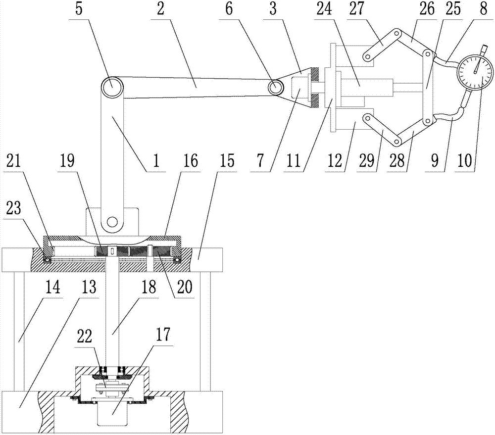
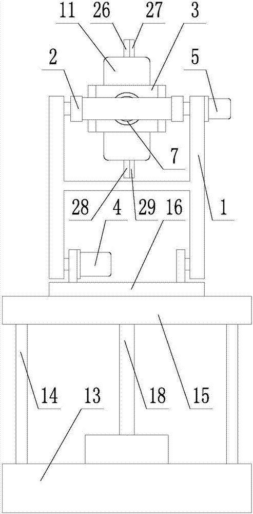
[0017] Such as figure 1 , 2 As shown, a thickness detection device for sheet metal stamping parts with variable thickness includes a rotary base, a large arm 1, a small arm 2, a wrist 3 and a claw; one end of the large arm 1 is hinged on the rotary base, and A boom drive motor 4 for driving the swing of the boom 1 is arranged at the hinge point; Forearm drive motor 5; the other end of the forearm 2 is hinged to one end of the wrist 3, and a wrist drive motor 6 for driving the swing of the wrist 3 is provided at the hinge point; the other end of the wrist 3 is fixed with a claw Rotary drive motor 7, described claw root 11 is fixedly connected with the motor shaft of claw rotary drive motor 7; Two measuring fingers are arranged at the front end of described claw palm 12, respectively denoted as main measuring finger 8 and Auxiliary m...


PUM


Abstract

A thickness detection device for variable-thickness sheet stamping parts comprises a rotary base, a large arm, a small arm, a wrist and a gripper. One end of the large arm is hinged to the rotary base, and a large arm driving motor used for driving the large arm to swing is arranged at the hinge point; the other end of the large arm is hinged to one end of the small arm, and a small arm driving motor used for driving the small arm to swing is arranged at the hinge point; the other end of the small arm is hinged to one end of the wrist, and a wrist driving motor used for driving the wrist to swing is arranged at the hinge point; a gripper rotation driving motor is fixedly mounted at the other end of the wrist, and the root of the gripper is fixedly connected with a motor shaft of the gripper rotation driving motor. The front end of a palm portion of the gripper is provided with two measurement fingers namely a main measurement finger and an auxiliary measurement finger, a dial gauge is fixedly mounted at the fingertip of the main measurement finger, and a measurement head of the dial gauge is matched with the fingertip of the auxiliary measurement finger. The main measurement finger and the auxiliary measurement finger are connected with the palm portion of the gripper through a measurement finger opening-closing driving mechanism.

Description

technical field [0001] The invention belongs to the technical field of plate thickness detection, and in particular relates to a thickness detection device for plate stamping parts with variable thickness. Background technique [0002] Stamping parts of variable thickness plates usually have special geometric shapes, and in some special fields, the thickness and dimension requirements for stamping parts of variable thickness plates are very strict, so the products must pass thickness inspection before leaving the factory. [0003] At present, the measuring tools used for sheet thickness detection are mainly micrometers and vernier calipers. However, due to the special geometry of sheet metal stamping parts with variable thickness, there are often some key parts that cannot be directly measured by traditional measuring tools. Therefore, only Indirect measurement is carried out by other tools, and the measurement accuracy of indirect measurement method is low. [0004] In add...

Claims


Application Information

Patent Timeline
IPC IPC(8): G01B5/06
CPCG01B5/06
Inventor 张华伟吴家恒吴佳璐
Owner 东北大学秦皇岛分校
Learn More