Position sensor and changeable capacitance module of same

A capacitive component and variable technology, applied in the direction of instrument, electrical digital data processing, data processing input/output process, etc., can solve the problems of insignificant change of capacitance value, poor displacement sensitivity, and inability to be controlled by users.

Active Publication Date: 2017-08-29
TAIWAN ALPHA ELECTRONICS
View PDF4 Cites 3 Cited by
  • Summary
  • Abstract
  • Description
  • Claims
  • Application Information

AI Technical Summary

Problems solved by technology

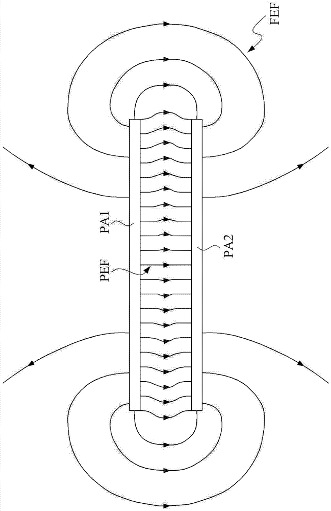
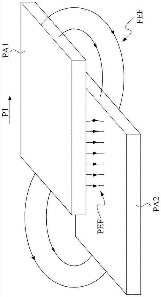
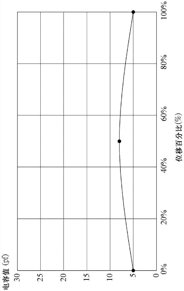
As shown in the figure, because an electric field will be generated between the two electrode plates due to the potential difference, in the existing technology, conductive metals such as copper are usually used as the material of the electrode plates, for example, the two metal copper electrode plates are made of The overlapped state (displacement is 0%) moves horizontally to complete overlap (displacement is 50%), and then moves away horizontally (displacement is 100%), and the capacitance value between the two metal copper electrode plates changes as Figure 3, it can be known that between two conductive metal plates The capacitance value changes less significantly
[0006] It can be seen from the above description that the magnitude of the capacitance value change due to the movement between the two metal electrode plates is not sensitive, so when the technology using the parallel capacitance effect is applied to When using a displacement sensor, the sensitivity of the displacement sensed by the capacitance change is poor, which cannot be accurately controlled by the user

Method used


Image

  • Position sensor and changeable capacitance module of same
  • Position sensor and changeable capacitance module of same
  • Position sensor and changeable capacitance module of same

Examples


Embodiment Construction

[0072] see Figure 4 to Figure 7 , Figure 4 A three-dimensional exploded schematic diagram showing a position sensor provided by a preferred embodiment of the present invention; Figure 5 A perspective exploded schematic diagram showing the variable capacitance component provided by the preferred embodiment of the present invention; Figure 6 A schematic plan view showing the variable capacitance component provided by the preferred embodiment of the present invention; Figure 7 A schematic circuit diagram of a capacitive sensing circuit provided by a preferred embodiment of the present invention is shown.

[0073] As shown in the figure, a position sensor 100 includes a variable capacitance component 1 , a circuit board 2 , a movable carrier 3 and a casing 4 .

[0074] The variable capacitance device 1 includes a substrate 11 and a dielectric cover 12 . The substrate 11 includes a substrate body 111 , a ground electrode 112 , and two power electrodes 113 and 114 .

[007...


PUM

PropertyMeasurementUnit
Thicknessaaaaaaaaaa
Lengthaaaaaaaaaa
Widthaaaaaaaaaa

Abstract

The invention provides a position sensor and a changeable capacitance module of the same. The position sensor comprises the changeable capacitance module and a circuit board. The changeable capacitance module comprises a baseplate and a dielectric coupling substance, wherein the baseplate comprises a baseplate body, a grounding electrode and two power source electrodes; the grounding electrode and the two power source electrodes are disposed on the baseplate body; the power source electrodes are disposed on the other side at an interval; the dielectric coupling substance and the two power source electrodes are set at an interval and the dielectric coupling substance is used to move along an action path. When the dielectric coupling substance moves along the action path, covering conditions for the dielectric coupling substance to cover the two power source electrodes and the grounding electrode will be changed. When a power source supplies power to the two power source electrodes in an alternating manner, a pair of alternating capacitance values sensed by a capacitance sensing circuit will vary with changes of the covering position, so that a relative position of the dielectric coupling substance on the action patch and the circuit board can be defined. According to the invention, the capacitance value is changed through changes of the covering rate of electrode coverage of the dielectric coupling substance.

Description

technical field [0001] The present invention relates to a position sensor and its variable capacitance assembly, in particular to a position sensor and its variable capacitance which utilizes the change of the area covered by at least two electrode sheets to be covered by a dielectric coupling to change the marginal capacitance components. Background technique [0002] Generally speaking, the existing potentiometers mainly use the change of the resistance value of the variable resistor as the basis of displacement sensing. The service life is reduced, so in the prior art, the displacement sensing technology based on the principle of capacitive effect is under development. [0003] see figure 1 , figure 1 A schematic plan view showing the capacitive effect generated between two electrode plates in the prior art. As shown in the figure, in common circuit configurations, electronic components such as capacitors are often seen, and the capacitive effect is mainly caused by t...

Claims


Application Information

Patent Timeline
IPC IPC(8): G06F3/044
CPCG06F3/044G06F2203/04112
Inventor 黄子轩刘韦良何朝仁何建志
Owner TAIWAN ALPHA ELECTRONICS
Why Eureka
Try Eureka