Independent winding and continuous pole-equipped permanent magnet motor

A technology for permanent magnet motors and windings, applied in magnetic circuits, synchronous machines, electrical components, etc., can solve the problems of complex processing and assembly technology, large amount of permanent magnets, etc., and achieve easy cooling, reduced amount of permanent magnets, and simple winding technology Effect

Inactive Publication Date: 2017-08-29
NANJING UNIV OF AERONAUTICS & ASTRONAUTICS
View PDF3 Cites 0 Cited by
  • Summary
  • Abstract
  • Description
  • Claims
  • Application Information

AI Technical Summary

Problems solved by technology

[0003] In order to solve the problem that the existing low-speed permanent magnet synchronous motor has a large amount of permanent magnets and complex processing and assembly technology, the present invention proposes a large tooth slot continuous pole permanent magnet motor

Method used


Image

  • Independent winding and continuous pole-equipped permanent magnet motor
  • Independent winding and continuous pole-equipped permanent magnet motor
  • Independent winding and continuous pole-equipped permanent magnet motor

Examples


Embodiment approach 1

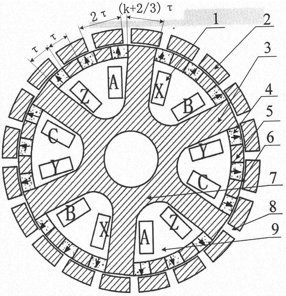
[0021] Such as figure 1 As shown, this embodiment is a three-phase external rotor independent winding continuous pole permanent magnet motor. It includes stator assembly, rotor assembly and air gap. The stator assembly consists of the armature core, armature windings and permanent magnets. The armature core includes large teeth 3, small teeth 5 and armature core yoke 7 structures. The large teeth 3 of the armature core and the yoke 7 form Q (Q=3k, k is an integer) large slots 9, and the armature winding 1 is arranged in the slots. The formed large groove 9 opening positions are provided with permanent magnets 4 and small teeth 5 arrays, and the permanent magnets 4 and small teeth 5 iron core blocks are arranged alternately, and the magnetization direction of all permanent magnets 4 is outward along the radial direction (or both Inward), the number of permanent magnet blocks is N (N=2I+1, I is an integer), the number of small teeth 5 is (N-1), and the position near the armat...

Embodiment approach 2

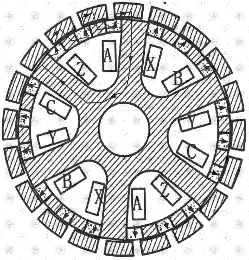
[0027] Such as Figure 4 As shown, the difference between the present embodiment and the first embodiment is that the discrete rotor core 2 is fixed by a sleeve 10, and the sleeve is made of a non-magnetic material.

Embodiment approach 3

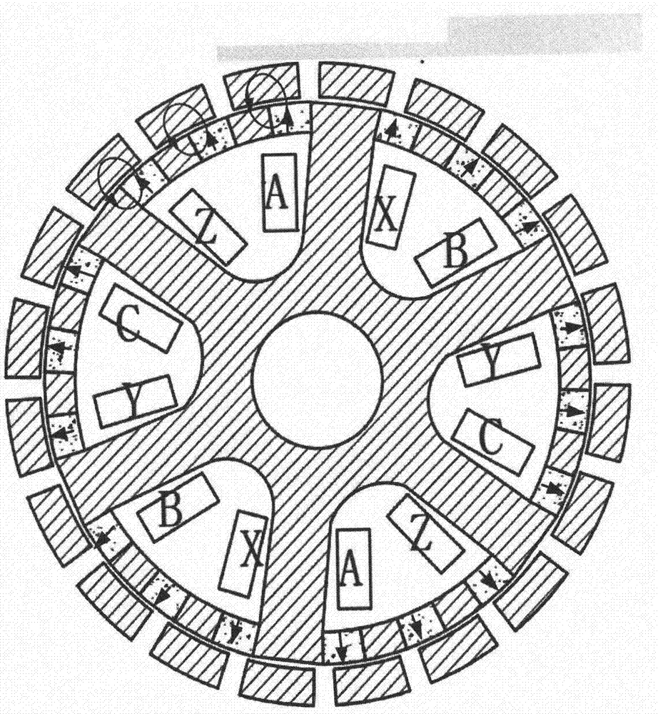
[0029] Such as Figure 5 As shown, the difference between this embodiment and the first embodiment is that the independent winding continuous pole permanent magnet motor adopts the inner rotor structure scheme. The armature winding 1-1, armature core large teeth 3-1, small teeth 5-1, and armature core yoke 7-1 are located on the outer circle of the motor, and the opening direction of the large slot 9 is along the direction of decreasing radius. The rotor core 2-1 and the gap 8-1 are located in the inner circle of the motor.


PUM


Abstract

The invention provides an independent winding and continuous pole-equipped permanent magnet motor, belongs to the technical field of a motor, and aims to solve the problems of high usage amount of permanent magnets and low torque density of the current low-speed permanent magnet motor. The permanent magnet motor comprises a stator assembly, a rotor assembly and air gaps; the stator assembly comprises an armature iron core, armature windings and permanent magnets; the armature iron core comprises big teeth, small teeth and a yoke structure; the big teeth and the yoke structure form big grooves; the armature windings are arranged in the corresponding grooves; the permanent magnets and the small teeth are alternately arranged in the opening positions of the big grooves; all the permanent magnets have the same magnetizing direction; the arc length of each small tooth and each permanent magnet is <tau> (<tau> is polar distance); the rotor assembly comprises rotor magnetic conducting iron cores and non-magnetic-conducting gaps; and the total arc length of the single rotor magnetic conducting iron core and the gap is 2<tau>. The motor adopts a multi-pole and less-groove structure, and the rotor is simple in structure; compared with the conventional N-S permanent magnet magnetic pole structure, the usage amount of the permanent magnets is greatly reduced; and the output torque is ensured while the motor cost can be highly lowered.

Description

technical field [0001] The invention belongs to the field of motors, in particular to a continuous pole permanent magnet motor with independent windings. Background technique [0002] The direct drive system eliminates the intermediate reduction mechanism, making the system simple in structure and suitable for low-speed applications. Existing direct-drive low-speed permanent magnet motors generally adopt a multi-pole multi-slot structure, in which the NS poles are composed of permanent magnets or permanent magnet arrays with opposite magnetization directions, which makes this type of motor consume a large amount of permanent magnets and the cost of the motor is high. Moreover, the motors are usually arranged with multi-poles and multi-slots, which makes the winding process complicated and the reliability reduced. Contents of the invention [0003] In order to solve the problems of large consumption of permanent magnets and complex processing and assembling technology of t...

Claims


Application Information

Patent Timeline
Patent Type & Authority Applications(China)
IPC IPC(8): H02K1/17H02K1/14H02K21/38H02K16/04
CPCH02K1/17H02K1/146H02K16/04H02K21/38H02K2201/03H02K2213/03
Inventor 黄旭珍嵇天鹏钱振宇
Owner NANJING UNIV OF AERONAUTICS & ASTRONAUTICS
Why Eureka
Try Eureka