Shaft entering and withdrawing dual-purpose device for plastic packaging motor rotor

A technology of plastic-encapsulated motors and dual-purpose devices, which is applied in electromechanical devices, manufacturing motor generators, and adjusting/balancing rotors. It can solve problems such as difficulty in installing bearings, crushing fingers, and enlarged shaft heads, so as to avoid replacement equipment, improve production efficiency, and avoid finger crushing effects

Inactive Publication Date: 2017-08-29
CHANGSHA WUDAO IND DESIGN CO LTD
View PDF0 Cites 18 Cited by
  • Summary
  • Abstract
  • Description
  • Claims
  • Application Information

AI Technical Summary

Problems solved by technology

[0002] When the motor rotor and the rotor shaft are assembled into the shaft, due to the interference fit between the rotor shaft and the motor rotor, a large force is required to make the motor rotor fit into the shaft. In the prior art, the motor rotor and the rotor shaft are The rotor shaft is pressed into the motor rotor by a press-fitting machine. However, due to the need to ensure the production of motors in batches, air-conditioning motor manufacturers often have no equipment to insert the shaft into the shaft during prototype production. Prototype makers often use manual shaft insertion. The efficiency is low, and it is easy to cause finger crushing, and the manual shaft insertion will easily cause the shaft head to become larger, making it difficult to install the bearing, which cannot meet the requirements of the prototype rotor production, and the current hydraulic machine cannot perform shaft insertion and withdrawal at the same time

Method used


Image

  • Shaft entering and withdrawing dual-purpose device for plastic packaging motor rotor
  • Shaft entering and withdrawing dual-purpose device for plastic packaging motor rotor
  • Shaft entering and withdrawing dual-purpose device for plastic packaging motor rotor

Examples


Embodiment Construction

[0021] The technical scheme of this patent is described in further detail below in conjunction with specific embodiments

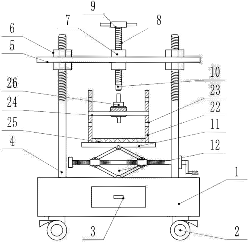
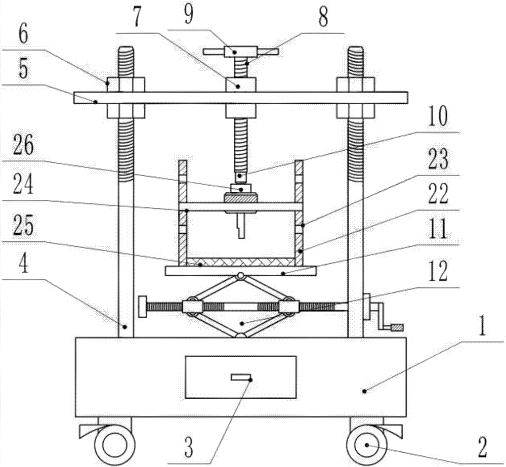
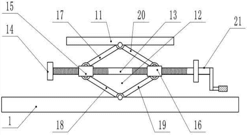
[0022] see Figure 1-4 , a dual-purpose device for entering and withdrawing the shaft of a plastic-encapsulated motor rotor, including a machine platform 1, a tool box 3, an adjusting screw 4, a support plate 5, a screw A8, a rotating handle 9, an extrusion head 10, a lifting platform 11, a lifting Device 12, fixed frame 22 and pressure nozzle 26, universal wheels 2 are fixedly installed on the lower side of the machine table 1, and there are at least four sets of universal wheels 2, and limited locking devices are installed on the universal wheels 2 to prevent the device from Movement occurs during work; the inside of the machine table 1 is a hollow structure, and a tool box 3 is slidably installed inside the machine table 1 through a chute. Adjusting screw 4 is fixedly installed, at least four groups of adjusting screw 4 are arranged, and the upper and ...


PUM


Abstract

The invention discloses a shaft entering and withdrawing dual-purpose device for a plastic packaging motor rotor. The shaft entering and withdrawing dual-purpose device comprises a machine table, a tool box, an adjustment screw rod, a supporting plate, a lead screw A, a rotary handle, an extrusion head, a lifting platform, a lifting device, a fixed frame and a pressure nozzle; a lead screw sleeve is fixedly arranged at a central position of the supporting plate; the lead screw A is in screw connection inside the lead screw sleeve; the rotary handle is fixedly arranged at an upper end of the lead screw A, and the extrusion head is fixedly arranged at a lower end of the lead screw A; the lifting device is fixedly arranged on the machine table; a plurality of groups of limiting grooves are formed at two sides of the fixed frame; and limiting plates are arranged on the limiting groove in an insertion manner. According to the device, under the condition of not replacing equipment, the shaft entering and withdrawing work are performed, and the repair personnel is prevented from frequently replacing the equipment; and meanwhile, through the rotary handle, the lead screw moves downward to implement extrusion on a rotating shaft, so compared with manual shaft withdrawing, the device is more time-saving and labor-saving; and the lifting platform is provided such that the repair personnel can perform the shaft entering and withdrawing work on different lengths of the rotating shafts conveniently.

Description

technical field [0001] The invention relates to the field of motors, in particular to a dual-purpose device for entering a shaft and withdrawing a rotor of a plastic-sealed motor. Background technique [0002] When the motor rotor and the rotor shaft are assembled into the shaft, due to the interference fit between the rotor shaft and the motor rotor, a large force is required to make the motor rotor fit into the shaft. In the prior art, the motor rotor and the rotor shaft are The rotor shaft is pressed into the motor rotor by a press-fitting machine. However, due to the need to ensure the production of motors in batches, air-conditioning motor manufacturers often have no equipment to insert the shaft into the shaft during prototype production. Prototype makers often use manual shaft insertion. The efficiency is low, and it is easy to cause finger crushing, and the manual shaft insertion will easily cause the shaft head to become larger, making it difficult to install the be...

Claims


Application Information

Patent Timeline
Patent Type & Authority Applications(China)
IPC IPC(8): H02K15/16H02K15/00
CPCH02K15/16H02K15/0006
Inventor 吴小明
Owner CHANGSHA WUDAO IND DESIGN CO LTD
Why Eureka
Try Eureka