
Microwave receiver and multi-antenna switching diversity reception method

A microwave receiver and receiving antenna technology, applied in the field of unmanned aerial vehicle communication, can solve problems affecting the endurance and thrust-to-weight ratio of unmanned aerial vehicles, affecting the integration degree of unmanned aerial vehicles and the weight of airborne equipment, increasing the scale of hardware circuit design, Cost and power consumption issues, to achieve the effect of improving endurance, easy implementation, and reducing multipath fading and distortion

Inactive Publication Date: 2017-08-29
FRSKY ELECTRONICS CO LTD
View PDF5 Cites 1 Cited by
  • Summary
  • Abstract
  • Description
  • Claims
  • Application Information

AI Technical Summary

Problems solved by technology

[0003] At present, the commonly used diversity technology is selective diversity. Selective diversity requires multiple receiver branches. By continuously making logical selections between the output signals of each receiver branch based on threshold judgments, the best output is selected. The signal is the final output, but the application of this diversity technology will increase the scale, cost and power consumption of the hardware circuit design while improving the communication quality and reliability. When the diversity technology is applied to the field of drones, it will Seriously affect the integration of drones and the weight of airborne equipment, thus affecting the endurance and thrust-to-weight ratio of drones

Method used


Image

  • Microwave receiver and multi-antenna switching diversity reception method
  • Microwave receiver and multi-antenna switching diversity reception method
  • Microwave receiver and multi-antenna switching diversity reception method

Examples


Embodiment Construction

[0019] The specific embodiments of the present invention will be further described below in conjunction with the accompanying drawings.

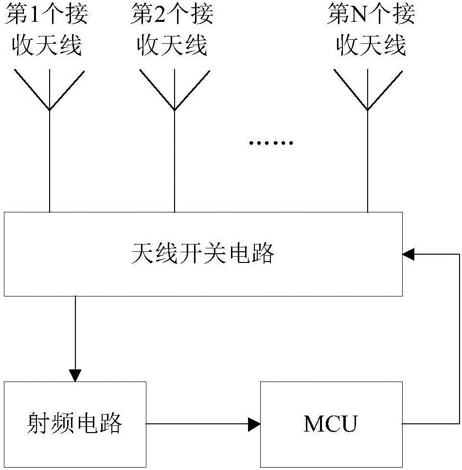
[0020] Such as figure 1 As shown, it shows a schematic structural diagram of a microwave receiver disclosed in the present invention, which is usually used in unmanned aerial vehicles. The microwave receiver includes: N receiving antennas, antenna switch circuits, radio frequency circuits and MCU (Microcontroller Unit, micro control unit), where the radio frequency circuit is usually a radio frequency chip, which is used to despread, demodulate, and restore data packets to the received radio frequency signal. The radio frequency signal is decoded and output. One end of the antenna switch circuit is connected to one of the N receiving antennas, the other end of the antenna switch circuit is connected to the input end of the radio frequency circuit, the output end of the radio frequency circuit is connected to the input end of the MCU, and th...


PUM


Abstract

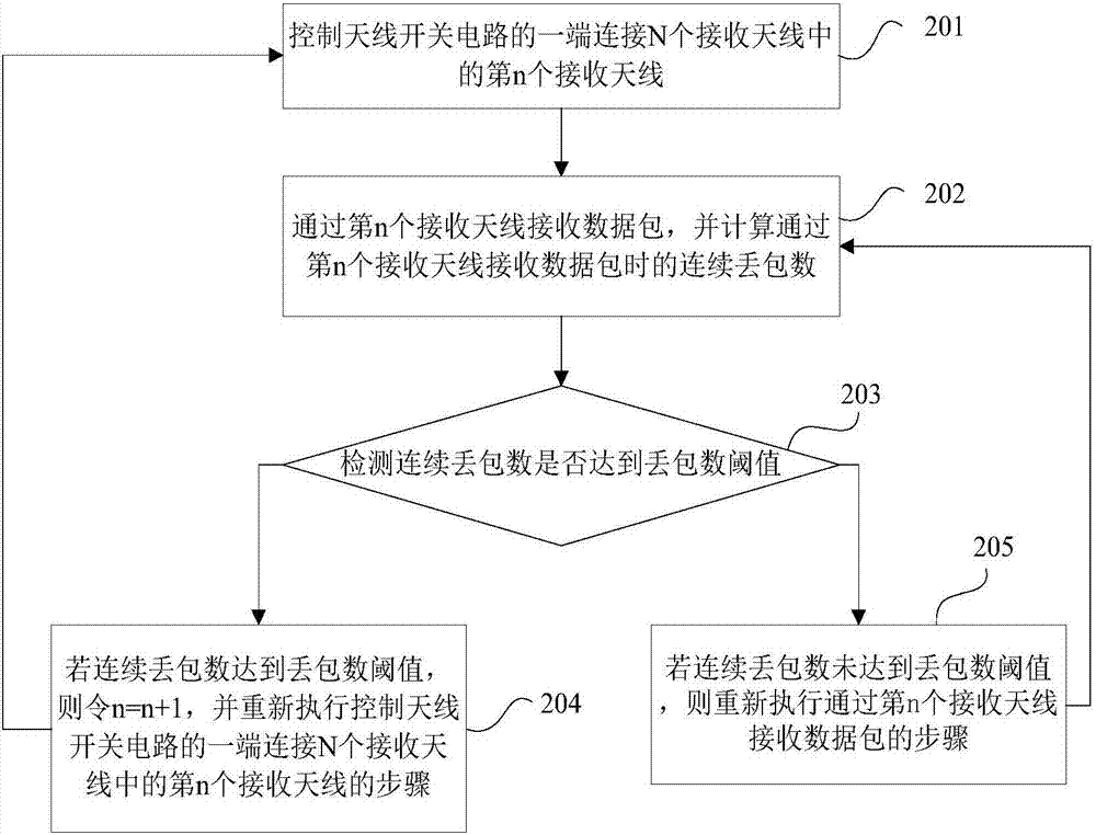
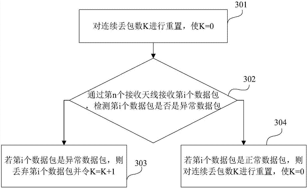
The present invention discloses a microwave receiver and multi-antenna switching diversity reception method, and relates to the unmanned aerial vehicle communication field. The method comprises: controlling one end of the antenna switching circuit in a microwave receiver to connect with the nth receiving antenna in N receiving antennas, n is a positive integer and the initial value of the n is 1, receiving a data packet through the nth receiving antenna, calculating the number of consecutive lost datagrams when the nth receiving antenna receives data packets, detecting whether the number of consecutive lost datagrams reaches the threshold of the number of packet loss or not, and if the number of consecutive lost datagrams reaches the threshold of the number of packet loss, defining n=n+1, and repeatedly executing the step of controlling one end of the antenna switching circuit being connected with the nth receiving antenna in the N receiving antennas. The comparison of the number of consecutive lost datagrams and the preset threshold of the number of packet loss is taken as a switching condition, the logic is simple, No extra hardware modules are required, and the system power consumption and the hardware scale are reduced while the multi-path fading and distortion in the multi-path transmission process.

Description

technical field [0001] The invention relates to the field of unmanned aerial vehicle communication, in particular to a microwave receiver and a multi-antenna switching diversity receiving method thereof. Background technique [0002] In microwave communication, communication quality and reliability are affected by many factors. The development of spread spectrum technology (mainly including direct sequence spread spectrum, frequency hopping and other derived spread spectrum technologies) has greatly improved the anti-interference ability of communication systems, but Multipath fading caused by multipath transmission is an irreversible adverse effect in microwave communication systems. In order to improve the stability and reliability of channel transmission under multipath fading, diversity technology is a commonly used anti-fading technology. [0003] At present, the commonly used diversity technology is selective diversity. Selective diversity requires multiple receiver br...

Claims


Application Information

Patent Timeline
IPC IPC(8): H04B1/16H04B7/0408
CPCH04B1/16H04B7/0408
Inventor 邵波
Owner FRSKY ELECTRONICS CO LTD
Learn More