Check patentability & draft patents in minutes with Patsnap Eureka AI!

Variable capacity compressor

A displacement type, compressor technology, used in liquid variable capacity machinery, mechanical equipment, machines/engines, etc., can solve problems such as no pressure drop, inability to perform discharge capacity control, etc., to achieve the effect of improving start-up performance

Inactive Publication Date: 2017-08-29
VALEO JAPAN CO LTD
View PDF3 Cites 2 Cited by
  • Summary
  • Abstract
  • Description
  • Claims
  • Application Information

AI Technical Summary

Problems solved by technology

Therefore, until all the liquid refrigerant is vaporized and discharged from the suction passage, the pressure of the control pressure chamber, that is, the crank chamber does not drop, and the discharge capacity control cannot be performed (discharge capacity does not increase).

Method used


Image

  • Variable capacity compressor
  • Variable capacity compressor
  • Variable capacity compressor

Examples


Embodiment Construction

[0041] Hereinafter, embodiments of the present invention will be described with reference to the drawings.

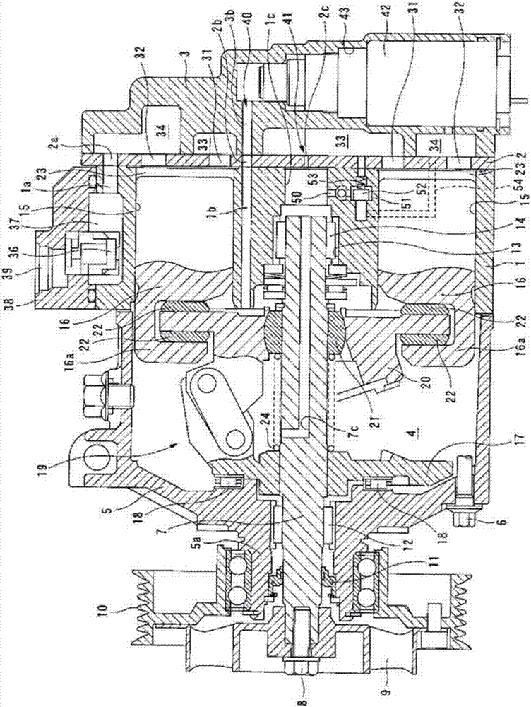
[0042] exist figure 1 and figure 2 In , a clutchless variable displacement compressor is shown that is driven by a power source such as an engine. This variable displacement type compression mechanism has a cylinder block 1, a rear cover 3 assembled on the rear side (right side in the figure) of the cylinder block 1 via a valve plate 2, so that the front side (left side in the figure) of the cylinder block 1 The front cover 5, cylinder body 1, valve plate 2 and rear cover 3 are fastened in the axial direction by fastening bolts 6 to form a compressor shell.

[0043] A drive shaft 7 with one end protruding from the front cover 5 runs through the control pressure chamber 4 separated by the front cover 5 and the cylinder body 1 . A drive pulley 10 is connected to a portion of the drive shaft 7 protruding from the front cover 5 , and the drive pulley 10 is rotatably e...


PUM


Abstract

[Problem] The objective of the present invention is to provide a variable capacity compressor with which the startup performance of the compressor can be improved, with which it is possible to reduce the amount of refrigerant that circulates internally during an intermediate stroke, and with which it is possible to eliminate the risk that contaminants or the like in the refrigerant will render it impossible to control the compressor. [Solution] This variable capacity compressor is provided with: an open passage 50 which communicates with a control pressure chamber 4 and a suction intake chamber 33; and a valve accommodating chamber 51 formed in the open passage. The open passage 50 has a configuration comprising: an upstream side open passage 50a communicating with the control pressure chamber 4 and the valve accommodating chamber 51, and a downstream side open passage 51b communicating with the valve accommodating chamber 51 and the suction intake chamber 33. The variable capacity compressor is provided with: a valve body 52 accommodated in the valve accommodating chamber 51 in such a way as to open and close the downstream side open passage 50b; an urging means (spring 53) which urges the valve body 52 in a direction opening the downstream side open passage 50b; a discharging pressure introduction passage 54 which communicates with the valve accommodating chamber 51 and a discharge chamber; and a non-return valve 55 which is provided in the upstream side open passage 50a and which allows fluid to flow only from the control pressure chamber 4 to the valve accommodating chamber 51.

Description

technical field [0001] The present invention relates to a variable displacement compressor whose discharge capacity is variable by adjusting the pressure of the control pressure chamber, and more particularly relates to an A variable displacement compressor that adjusts the pressure of the control pressure chamber with the suction passage of the suction chamber. Background technique [0002] The variable displacement compressor adopts a mechanism that adjusts the pressure of the control pressure chamber to change the inclination angle of the swash plate to adjust the stroke amount of the piston, thereby making the discharge capacity variable. As such a compressor, a structure is known in which the control pressure chamber and the suction chamber are communicated through the suction passage, and a control valve is provided on the air supply passage connecting the discharge chamber and the control pressure chamber, and the opening and closing of the air supply passage is contr...

Claims


Application Information

Patent Timeline
IPC IPC(8): F04B27/18
CPCF04B27/18F04B2027/1895
Inventor 雨森雅典大泽仁
Owner VALEO JAPAN CO LTD
Features
  • R&D
  • Intellectual Property
  • Life Sciences
  • Materials
  • Tech Scout
  • Unparalleled Data Quality
  • Higher Quality Content
  • 60% Fewer Hallucinations
Learn More