Damper apparatus

A technology of vibration damping device and shock absorber, which is applied to transmission devices, fluid transmission devices, inertial effect shock absorbers, etc., can solve the problems of reducing vibration damping performance and the like

Active Publication Date: 2017-08-29
AISIN AW INDUSTRIES CO LTD +1
View PDF6 Cites 4 Cited by
  • Summary
  • Abstract
  • Description
  • Claims
  • Application Information

AI Technical Summary

Problems solved by technology

Therefore, in the above-mentioned conventional torsional vibration damper, in a state where the amplitude of the vibration transmitted from the damper spring device to the output member is reduced, a large torque is applied to the output member from the rotating inertial mass damper, On the contrary, there is concern about the reduction of vibration damping performance

Method used


Image

  • Damper apparatus
  • Damper apparatus
  • Damper apparatus

Examples


Embodiment Construction

[0019] Next, the mode for implementing the present invention will be described with reference to the drawings.

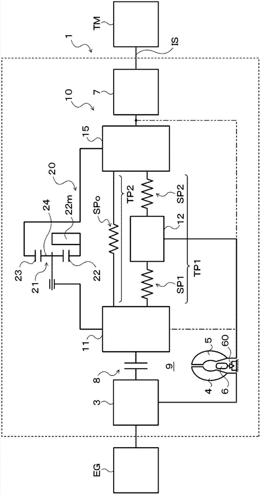
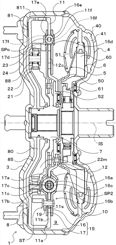
[0020] figure 1 It is a schematic configuration diagram showing a starting device 1 including a vibration damping device 10 according to an embodiment of the present invention, figure 2 It is a cross-sectional view showing the starting device 1. The starting device 1 shown in the above drawings is mounted on a vehicle equipped with an engine (internal combustion engine) EG as a prime mover. In addition to the vibration damping device 10, the starting device 1 is connected to the crankshaft of the engine EG and transmits torque from the engine EG. The front cover 3 as the input part, the pump wheel (input side fluid transmission member) 4 fixed to the front cover 3, the coaxial and rotatable turbine (output side fluid transmission member) 5 with the pump wheel 4, and the vibration damping device 10 is connected to and fixed to an automatic transmission (AT) or a conti...


PUM


Abstract

A damper apparatus (10Y) includes a first inner spring (SP1') for transmitting torque between a drive member (11Y) and an intermediate member (12Y), a second inner spring (SP2') for transmitting torque between the intermediate member (12Y) and a driven member (15Y), and a rotational inertial mass damper (20Y) having a sun gear (22) as a body of mass that rotates according to the relative rotation between the drive member (11Y) and the driven member (15Y), the rotational inertial mass damper (20Y) being provided in parallel with a torque transmission path (TP) that includes the intermediate member (12Y) and first and second inner springs (SP1, SP2), and the damping ratio Zeta of the intermediate member (12) being a value of less than 1, as determined on the basis of the inertia moment (J2) of the intermediate member (12Y) and the rigidities (k1, k2) of the first and second inner springs (SP1', SP2').

Description

Technical field [0001] The present invention relates to a vibration damping device, which includes an input member, an output member, and an elastic body that transmits torque between the input member and the output member. Background technique [0002] Conventionally, a torsional vibration damper including a damper spring device having a plurality of springs arranged in the circumferential direction and a rotating inertial mass damper has been known (for example, refer to Patent Document 1). In this torsional vibration damper, the damper spring device has a plurality of sliders, which are respectively arranged between adjacent springs, and are supported by the damper element (input member) on the drive side as a whole free outer peripheral surface. slide. In addition, the rotating inertial mass damper includes: a damper element on the driving side of the sun gear that rotates integrally with the turbine shell of the turbine wheel and includes a planetary gear, and rotates integ...

Claims


Application Information

Patent Timeline
Patent Type & Authority Applications(China)
IPC IPC(8): F16H45/02F16F7/10F16F15/134
Inventor 吉川卓也小川亚树木下友则勘山裕司山口诚伊藤一能长井大树轮嶋雅树坂本贵生伊藤和广泷川由浩大井阳一
Owner AISIN AW INDUSTRIES CO LTD
Why Eureka
Try Eureka