Visualization of electrical loads

A technology of electrical load and load information, applied in the direction of electrical components, circuits, electrical switches, etc., can solve the problems of complicated installation and use, inability to obtain an overview of electrical equipment, use restrictions, etc., to achieve the effect of easy setting and operation

Inactive Publication Date: 2017-08-29
ENERGYBOX
View PDF9 Cites 0 Cited by
  • Summary
  • Abstract
  • Description
  • Claims
  • Application Information

AI Technical Summary

Problems solved by technology

While these devices are useful in identifying electrical devices causing particularly high electrical loads, they are relatively complex to install and use, resulting in high installation costs or limited use
Furthermore, these devices do not allow to obtain an overview of the overall electrical equipment of the premises

Method used


Image

  • Visualization of electrical loads
  • Visualization of electrical loads
  • Visualization of electrical loads

Examples


Embodiment Construction

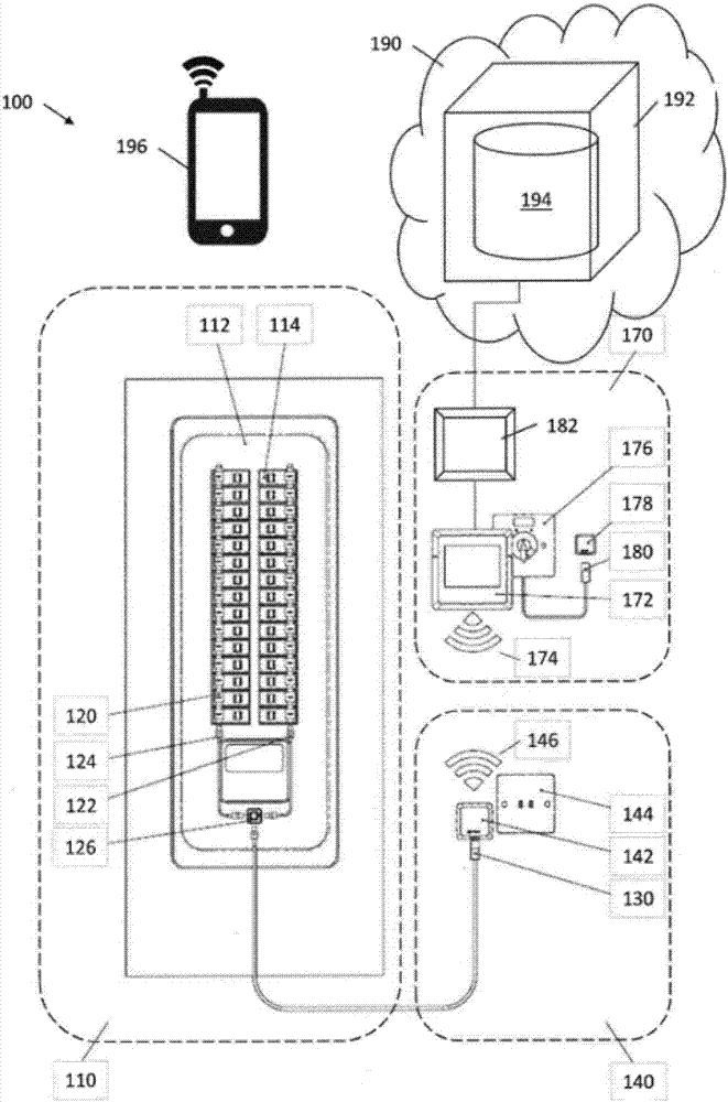
[0020] figure 1 A schematic diagram of an energy metering system 100 according to an embodiment of the invention is shown. The energy metering system 100 includes three fixedly installed subsystems, namely the sensor subsystem 110 , the data acquisition subsystem 140 and the data analysis subsystem 170 . In other embodiments, several of these subsystems may be omitted, combined or divided into further subsystems. Additionally, the energy metering system 100 includes a cloud service 192 and a portable device 196 .

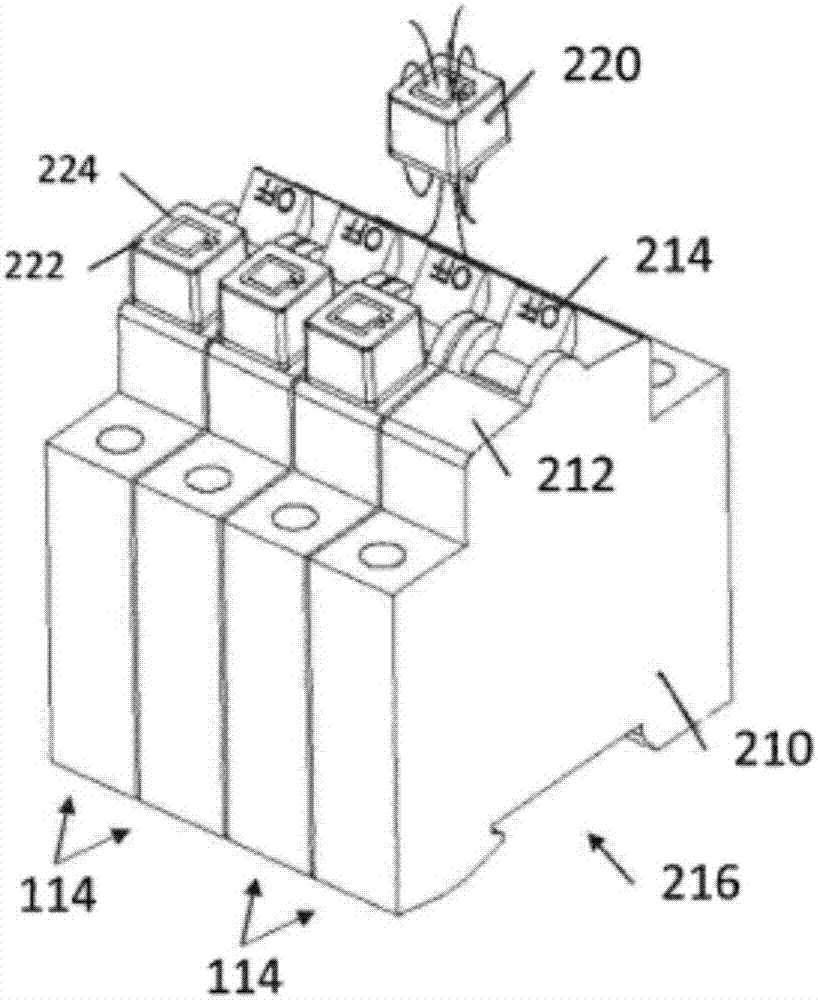
[0021] According to the described embodiment, the sensor subsystem 110 is mounted directly on a conventional switchboard 112 or in an enclosed fuse box. exist figure 1 In the illustrated embodiment, the switchboard 112 includes two vertical rows of circuit breakers 114 . Of course, in other embodiments, the circuit breakers 114 may be arranged horizontally or in a different number of rows and columns. Each circuit breaker 114 is connected to a power supply line...


PUM


Abstract

A visualization system for visualizing electrical loads of an electrical distribution panel is disclosed in one embodiment. The system includes a sensor arrangement for sensing an electrical load of a plurality of electrical circuits protected by corresponding circuit breakers of the distribution panel and for providing corresponding sensor data, a data processing system for aggregating and storing the sensor data of the sensor arrangement, and a portable device. The portable device includes an image capturing unit and a display screen. It is configured to obtain a live image of at least a part of the electrical distribution panel from the image capturing unit, to identify individual circuit breakers within the live image, to obtain load information at least for the identified circuit breakers from the data processing system and to display the obtained load information in a structured way on the display screen of the portable device.

Description

[0001] Cross References to Related Applications [0002] This application is related to the following co-pending applications. Copending U.S. Application No. 14 / 586,710, filed December 30, 2014 (Attorney Docket No. EBL-001), entitled "Energy metering system with self-powered sensors," and filed December 30, 2014 Co-pending U.S. Application No. 14 / 586,740, filed (Attorney Docket No. EBL-003), and entitled "Energy metering system and method for its calibration," discloses the inventive energy metering system disclosed herein. other aspects. In particular, the application EBL-001 provides detailed information on the power supply of the sensors of the sensor system. Application EBL-003 provides details on the calibration and operation of energy metering systems. The aforementioned co-pending applications are incorporated herein by reference. technical field [0003] The invention relates to an energy metering system for visualizing electrical loads of a switchboard. In partic...

Claims


Application Information

Patent Timeline
IPC IPC(8): G01D4/00
CPCG01D4/00H01H9/167Y04S20/30G06F30/20
Inventor 迪尔克·拜纳
Owner ENERGYBOX
Why Eureka
Try Eureka