
Method for measuring asymmetry, inspection apparatus, photolithography system, and device manufacturing method

An asymmetric, inspection equipment technology, used in opto-mechanical equipment, microlithography exposure equipment, patterned surface photoengraving process, etc.

Active Publication Date: 2019-10-18
ASML NETHERLANDS BV
View PDF19 Cites 0 Cited by
  • Summary
  • Abstract
  • Description
  • Claims
  • Application Information

AI Technical Summary

Problems solved by technology

Therefore, obtaining optimal asymmetry measurements across a wide range of wavelengths remains a great challenge for hardware designers, manufacturers and operators of these instruments

Method used


Image

  • Method for measuring asymmetry, inspection apparatus, photolithography system, and device manufacturing method
  • Method for measuring asymmetry, inspection apparatus, photolithography system, and device manufacturing method
  • Method for measuring asymmetry, inspection apparatus, photolithography system, and device manufacturing method

Examples


Embodiment Construction

[0049] Before describing embodiments of the invention in detail, it is instructive to present an example environment in which embodiments of the invention may be practiced.

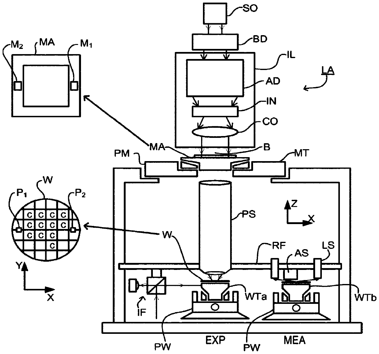
[0050] figure 1 A lithographic apparatus LA is schematically depicted. The apparatus comprises: an illumination system (illuminator) IL configured to condition a radiation beam B (e.g. UV radiation or DUV radiation); a patterning device support or support structure (e.g. a mask table) MT configured To support the patterning device (e.g., mask) MA, and connected to a first positioner PM configured to accurately position the patterning device according to certain parameters; two substrate tables (e.g., wafer stage) WTa and WTb, each configured to hold a substrate (e.g., a resist-coated wafer) W, and each connected to a second positioner PW configured to accurately position the substrate according to certain parameters; and a projection system ( For example, a refractive projection lens system) PS configu...


PUM


Abstract

Use the scatterometer in dark-field imaging mode to measure asymmetry-related parameters such as overlay. The same optical path is used for measurements on small grating targets, where the target is in two orientations to obtain separate measurements of the +1 and ‑1 diffraction orders. In this way, intensity scale differences (instrumental asymmetry) are avoided. However, additional intensity defects caused by stray light (virtual images) in the optical system cannot be avoided. The additional intensity issue is very much dependent on the ratio between the 0th order diffraction and the 1st order diffraction, and thus depends largely on the wafer (process) inversely. Calibration measurements (CM1 to CM4) are performed on several representative target gratings with deviations (+d, ‑d). The calibration measurements are performed not only with different wafer rotations (RZ=0, π), but also with complementary apertures (13N, 13S). A correction (δ, G) is calculated and applied to calculate a corrected asymmetry A' in order to reduce errors caused by stray light.

Description

[0001] Cross References to Related Applications [0002] This application claims priority to EP application 14199200.8, filed 19 December 2014, which is hereby incorporated by reference in its entirety. technical field [0003] The present invention relates to methods and apparatus for metrology that can be used to fabricate devices, eg by lithography, and to methods of fabricating devices using lithography. Background technique [0004] A lithographic apparatus is a machine that applies a desired pattern to a substrate, usually to a target portion of the substrate. A lithographic apparatus may be used, for example, in the manufacture of integrated circuits (ICs). In this case, a patterning device (which is alternatively referred to as a mask or reticle) may be used to generate the circuit pattern to be formed on the individual layers of the IC. The pattern can be transferred onto a target portion (eg, comprising a portion of a die, a die, or a plurality of dies) on a sub...

Claims


Application Information

Patent Timeline
Patent Type & Authority Patents(China)
IPC IPC(8): G03F7/20
CPCG03F7/70633G03F7/70941G06T7/11G06T7/0004G06T2207/30148
Inventor A·富克斯P·H·瓦德尼尔A·辛格M·达尔方索H·D·波斯
Owner ASML NETHERLANDS BV
Learn More