Method and system for manufacture of compressed coil

A technology of compressing coils and coils, which is applied in the field of manufacturing compression coils, can solve the problems of damaged coil terminals, unsuitable for stranded wires or litz wires, etc., and achieve the effect of increasing torque density and eliminating damage

Active Publication Date: 2017-08-29
ADVANCED ELECTRIC MASCH GRP LTD
View PDF7 Cites 3 Cited by
  • Summary
  • Abstract
  • Description
  • Claims
  • Application Information

AI Technical Summary

Problems solved by technology

[0007] However, current compression coil manufacturing techniques may not be suitable for stranded or litz wire because they damage the coil terminations, especially if the coil leads are not handled carefully during compression of the coil or during the winding or compression process in the case of

Method used


Image

  • Method and system for manufacture of compressed coil
  • Method and system for manufacture of compressed coil
  • Method and system for manufacture of compressed coil

Examples


Embodiment Construction

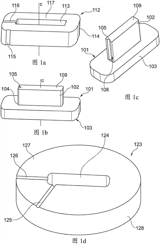
[0074] Figure 1a , Figure 1b , Figure 1c and Figure 1d Respectively showing the stamped top, the bobbin, from another angle Figure 1c An example of a bobbin and die used during the method of manufacturing a compression coil.

[0075] In this example, a bobbin 101 includes a central portion (shaft) 102 and a flange 103 at a first end 104 of the shaft 102 (eg Figure 1b and Figure 1c shown). The shaft 102 has a generally rectangular cross-sectional shape and a suitable length so that wire is wound around the shaft to form a coil. In this example, the bobbin is formed from a high strength tool steel material.

[0076] The flange 103 has a cross-sectional shape larger than that of the shaft 102 . In use, the flange 103 is sized and shaped to prevent the wrap wire from slipping off the first end 104 of the shaft 102 . The size and shape of the flange 103 may also or alternatively correspond to the desired shape of the surface of the compression coil. In this example,...


PUM


Abstract

A method of manufacturing a compressed coil and a system for holding a wire during the manufacture of a compressed coil are disclosed. The method includes providing a wire including a first lead section, a central section and a second lead section. The central section of the wire is wound around a bobbin to form a coil. A punch top is located over an end of the bobbin such that the end of the bobbin is located at least partially within a through-hole of the punch top. A second lead section of the wire is located within a groove in an outer surface of the punch top or bobbin and pressure is applied to the bobbin and / or punch top to compress the coil.

Description

technical field [0001] The present invention relates to methods and systems for manufacturing compression coils. In particular, but not exclusively, the invention relates to methods of compressing coils while maintaining the integrity of the coil terminals. Background technique [0002] There is an increasing demand for high power density electric motors in the automotive and aerospace industries. Such machines typically operate at high current densities and high speeds. [0003] The performance of modern high power density motors is often limited by a combination of high loss density and thermal resistance between the motor windings and the coolant. Some of these limitations can be addressed by increasing the fill factor in the motor windings. [0004] Compression coils can result in a higher fill factor than conventionally wound coils. The overall fill factor is defined as the ratio of the conductive cross-sectional area of ​​the wound electrical coil to the amount of ...

Claims


Application Information

Patent Timeline
Patent Type & Authority Applications(China)
IPC IPC(8): H01F41/06H01F41/04H02K15/04H02K15/00
CPCH01F41/04H01F41/06H02K15/0435H02K2213/12H02K2203/12H02K15/0068H01F41/098H02K15/0031Y10T29/49071
Inventor 克里斯托弗·大卫·曼宁詹姆斯·威德默理查德·马丁
Owner ADVANCED ELECTRIC MASCH GRP LTD
Why Eureka
Try Eureka