
Solar battery and solar battery module

A technology of solar cells and electrodes, applied in circuits, electrical components, photovoltaic power generation, etc., can solve problems such as battery warping, increased stress, and electrode peeling

Active Publication Date: 2017-08-29
KANEKA CORP
View PDF13 Cites 9 Cited by
  • Summary
  • Abstract
  • Description
  • Claims
  • Application Information

AI Technical Summary

Problems solved by technology

Since the moving distance of photocarriers generated on the semiconductor substrate becomes larger when the width of the semiconductor layer becomes larger, the loss due to carrier recombination increases
In addition, when the height of the electrode becomes larger, the stress at the interface between the electrode and the semiconductor layer becomes larger, causing warping of the battery or peeling of the electrode, etc.
Therefore, increasing the cross-sectional area of ​​the finger electrodes is limited to reduce the series resistance

Method used


Image

  • Solar battery and solar battery module
  • Solar battery and solar battery module
  • Solar battery and solar battery module

Examples


Embodiment Construction

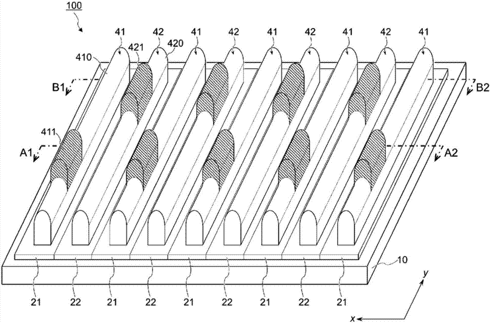
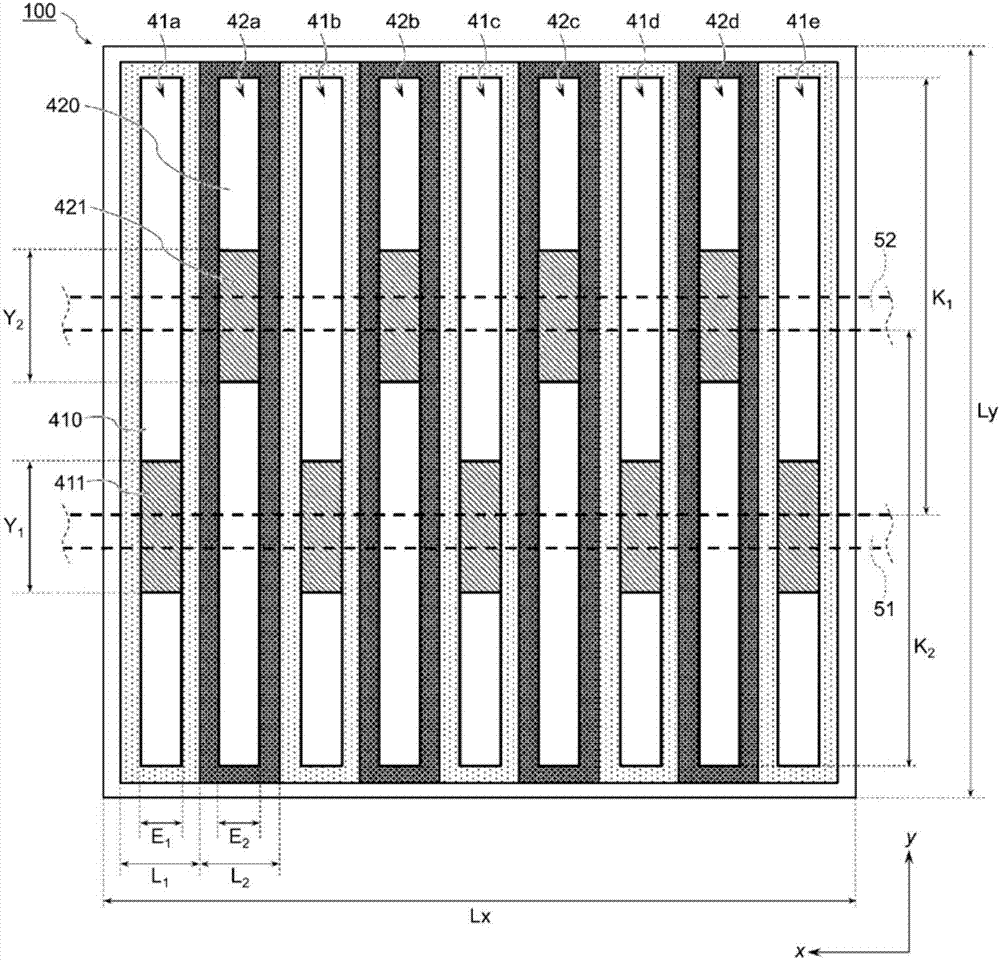
[0045] figure 1 It is a schematic perspective view of a back junction type solar cell according to one embodiment of the present invention. figure 2 yes figure 1 The top view of the upper side (the back side of the solar cell). Figure 3A yes figure 1 A sectional view at line A1-A2 of Figure 3B yes figure 1 Sectional view at line B1-B2. exist figure 2 , Figure 3A as well as Figure 3B In , the state in which the wiring members 51 and 52 are connected to the electrodes of the solar cell is indicated by a dotted line.

[0046] The solar cell 100 is on the back side of the semiconductor substrate 10 ( figure 1 The surface on the upper side) is provided with a first conductivity type layer 21 and a second conductivity type layer 22 . A first electrode 41 is provided on the first conductivity type layer 21 , and a second electrode 42 is provided on the second conductivity type layer 22 . The first electrode 41 and the second electrode 42 are separated and insula...


PUM


Abstract

A solar battery (100) is provided with: a first conductivity type layer (21) and a second conductivity type layer (22) which are disposed on a rear surface of a semiconductor substrate (10); first electrodes (41) disposed on the first conductivity type layer; and second electrodes (42) disposed on the second conductivity type layer. The first electrodes and the second electrodes are spaced apart from each other, and the first electrodes include a plurality of regions separated by the second electrodes disposed between the first electrodes. Each of the plurality of regions of the first electrodes includes a non-connection electrode portion (410) and a wiring connection electrode portion (411) having a greater electrode height than the non-connection electrode portion. In two adjacent first electrode regions, an imaginary line connecting the apex of the wiring connection electrode portion of one of the regions and the apex of the wiring connection electrode portion of the other region does not intersect the second electrode disposed between the two regions.

Description

technical field [0001] The invention relates to solar cells and solar cell modules. The present invention also relates to a method of testing a solar cell and a method of manufacturing a solar cell module. Background technique [0002] A general solar cell is a double-sided electrode type, and has electrodes on both the light-receiving surface and the back surface. On the other hand, a back-junction type solar cell has been developed as a solar cell free from light-shielding loss due to electrodes (for example, Patent Document 1). Since the back-junction type solar cell has electrodes only on the back side, there is no light-shielding loss due to the metal electrode on the light-receiving side, and it is expected to have high conversion efficiency. [0003] A back junction solar cell has a p-type semiconductor layer and an n-type semiconductor layer on the back side of a semiconductor substrate. Figure 7 Represents a back-junction solar cell in which a p-type semiconducto...

Claims


Application Information

Patent Timeline
Patent Type & Authority Applications(China)
IPC IPC(8): H01L31/0224H01L31/0747
CPCH01L31/0747H01L31/0516H01L31/022441Y02E10/547H01L31/022433H01L31/0682Y02E10/50H01L31/0224H01L31/0465
Inventor 吉河训太中野邦裕河崎勇人小西克典
Owner KANEKA CORP
Learn More