Light-emitting diode (LED) dimming driving system with silicon controlled bypass dimming circuit

A dimming circuit and dimming drive technology, which is applied in the field of LED lighting, can solve problems such as low power factor, complex structure, and poor compatibility, and achieve the effects of high power factor, easy commercialization, and improved efficiency and reliability

Active Publication Date: 2013-06-05
SHANGHAI UNIV
View PDF3 Cites 23 Cited by
  • Summary
  • Abstract
  • Description
  • Claims
  • Application Information

AI Technical Summary

Problems solved by technology

[0010] Aiming at the deficiencies existing in the existing LED thyristor dimming technology, the purpose of the present invention is to solve the complex structure of the existing LED thyristor dimming circuit, which is easy to generate a large number of harmonics, low power factor, low efficiency, easy to cause flicker, and For problems such as poor compatibility of LEDs, a LED dimming drive system with thyristor bypass dimming circuit is provided, which comprehensively utilizes the advantages of thyristor dimming and analog dimming to achieve simplicity and practicality, reduce harmonics, and improve power factor. , improve efficiency, solve flickering problem

Method used


Image

  • Light-emitting diode (LED) dimming driving system with silicon controlled bypass dimming circuit
  • Light-emitting diode (LED) dimming driving system with silicon controlled bypass dimming circuit
  • Light-emitting diode (LED) dimming driving system with silicon controlled bypass dimming circuit

Examples


Embodiment 1

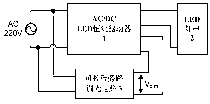
[0035] see figure 2 , the LED dimming driving system with thyristor bypass dimming circuit, including: AC / DC constant current driver (1) and LED lamp string (2). The input end of the AC / DC LED constant current driver (1) is connected to the AC mains AC, and the output end is connected to the LED light string (2);

[0036] There is a silicon controlled rectifier bypass dimming circuit (3), the input end of which is connected to the AC mains AC, and the output end is connected to the dimming interface of the AC / DC LED constant current driver (1);

[0037] The AC / DC LED constant current driver (1) obtains energy from AC mains, and outputs a constant current value to drive the LED light string (2); the AC / DC LED constant current driver (1) has There is an analog dimming interface, and the output current value is adjusted according to the analog voltage amplitude of the input dimming signal, thereby changing the brightness of the LED light string (2); the thyristor bypass dimming...

Embodiment 2

[0039] see Figure 4 , this embodiment is basically the same as Embodiment 1, the special feature is: the AC / DC LED constant current driver (1) is an AC / DC constant voltage circuit (1-1) connected with a DC / DC constant current circuit ( 1-2), the output end of the DC / DC constant current circuit (1-2) is connected to the LED light string (2), and the output end of the thyristor bypass dimming circuit (3) is connected to the DC / DC constant current circuit ( 1-2) Analog interface.

Embodiment 3

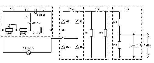
[0041] Such as Figure 4 As shown, the LED dimming drive system with thyristor bypass dimming circuit includes three parts: AC / DC constant voltage circuit 1-1, DC / DC constant current circuit 1-2, and thyristor bypass Circuit 3. The input end of the described AC / DC constant voltage circuit 1-1 is connected with the AC mains, and its output end is connected with the input end of the described DC / DC constant current circuit 1-2; the described DC / DC constant current The output end of the circuit 1-2 is connected in series with the LED lamp; the input end of the thyristor bypass dimming circuit 3 is connected to the AC mains, and the output end is connected to the DC / DC constant current circuit 1- 2 dimming port connection;

[0042] The AC / DC constant voltage circuit 1-1 obtains energy from the AC mains, and outputs a constant DC voltage value; the DC / DC constant current circuit 1-2 obtains energy from the AC / DC constant voltage circuit 1 The output terminal of -1 obtains energy...


PUM


Abstract

The invention relates to a light-emitting diode (LED) dimming driving system with a silicon controlled bypass dimming circuit. The LED dimming driving system with the silicon controlled bypass dimming circuit comprises an alternating current/direct current (AC/DC) LED constant current actuator and a LED light string, wherein the input end of the AC/DC LED constant current actuator is electrically connected with an alternating current electric supply, the output end of the AC/DC LED constant current actuator is connected with the LED light string, the silicon controlled bypass dimming circuit is arranged, the input end of the silicon controlled bypass dimming circuit is connected with the alternating current (AC) electric supply, and the output end of the silicon controlled bypass dimming circuit is connected with a dimming interface of the AC/DC LED constant current actuator. The AC/DC LED constant current actuator obtains energy from the AC electric supply, and outputs a constant current value to drive the LED light string. The AC/DC LED constant current actuator is provided with an analog dimming interface which is used for adjusting an output current value according to an analog voltage amplitude value of an input dimming signal so as to change luminance of the LED light string. According to the silicon controlled bypass dimming circuit, the input end of the silicon controlled bypass dimming circuit is connected with the AC electric supply, and the output end of the silicon controlled bypass dimming circuit generates a smooth direct current analog voltage signal to serve as a dimming signal which is input into the analog dimming interface of the AC/DC LED constant current actuator. The value of amplitude of the dimming signal output by the silicon controlled bypass dimming circuit can be adjusted by adjusting an adjustable knob of the silicon controlled bypass dimming circuit, and thus a current value and the luminance of the LED light string can be adjusted.

Description

technical field [0001] The invention relates to an LED dimming driver system, in particular to an LED dimming driver system with a thyristor bypass dimming circuit, belonging to the technical field of LED lighting. Background technique [0002] LED has the advantages of high luminous efficiency, long service life, and good stability, and is widely used in the field of lighting. When using LED lighting or LED backlight, it is often required to be able to adjust the brightness of the LED. However, despite the continuous development of LED dimming technology, the shortcomings in efficiency, reliability and compatibility have been hindering the service life and popularization of LED lighting systems. [0003] At present, LED dimming technology can be roughly divided into: [0004] (1) Digital dimming; (2) Analog dimming; (3) PWM dimming; (4) SCR dimming. [0005] LED digital dimming technology is that the external controller sends digital signals to the LED driver through the...

Claims


Application Information

Patent Timeline
Patent Type & Authority Applications(China)
IPC IPC(8): H05B37/02
Inventor 刘廷章曹凌云叶冰胡力元
Owner SHANGHAI UNIV
Why Eureka
Try Eureka