Plate mop and mop bucket

The technology of a flat mop and a mop bucket is applied in the field of ground sanitation and cleaning appliances, and can solve the problems of difficult production, time-consuming and laborious operation, and large volume of the bucket body.

Inactive Publication Date: 2017-09-01
ZHEJIANG XINGHAO PLASTIC
View PDF14 Cites 79 Cited by
  • Summary
  • Abstract
  • Description
  • Claims
  • Application Information

AI Technical Summary

Problems solved by technology

However, the flat mop has the following problems in use: the wet mop needs to be manually squeezed dry before use, and then the mop can be fixed on the flat mop for use; after use, the mop needs to be removed from the flat mop for manual cleaning And squeeze dry, not only the work efficiency is low, the labor intensity is high, but also the hands will be dirty when cleaning and squeezing dry, which can no longer meet the cleaning and sanitation requirements of the majority of users
Although this structure has fast cleaning speed, high efficiency and good effect, and does not need to be manually squeezed, it is hygienic and clean to use, but there are also the following problems: one is that cleaning and dehydration cannot be carried out alternately, and the water in the bucket needs to be drained when cleaning and dehydration are completed. Dehydration can only be carried out after part or all of it is discharged, and it cannot be operated continuously, which brings inconvenience to users; secondly, due to the long length of the flat drag, the volume of the barrel is also large, ...

Method used


Image

  • Plate mop and mop bucket
  • Plate mop and mop bucket
  • Plate mop and mop bucket

Examples


Embodiment approach

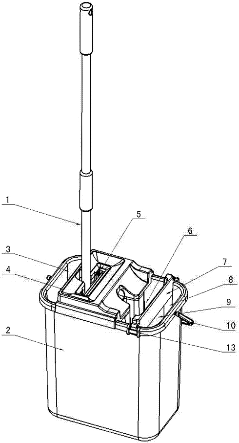
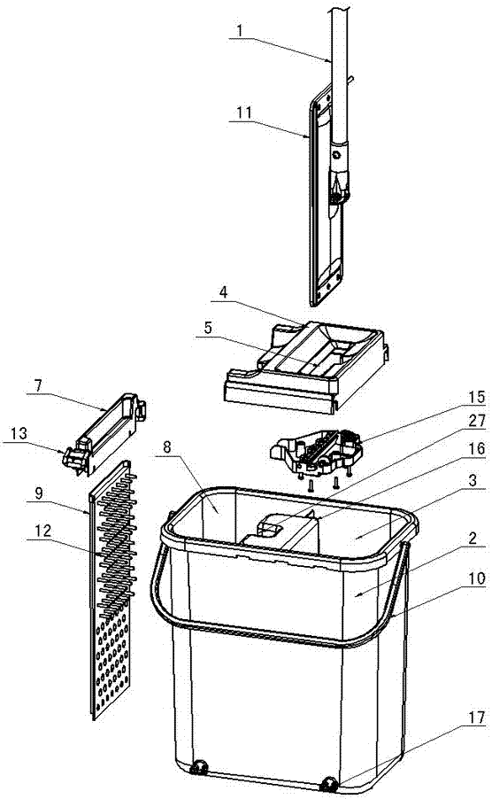
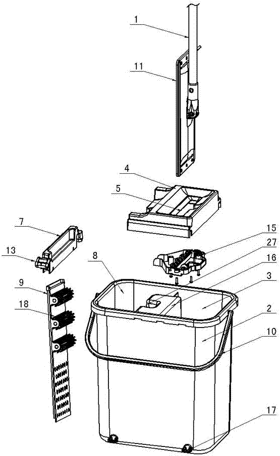
[0045] Figure 1 to Figure 5 Shown, for the present invention creates the first kind of specific embodiment of flat mop and mop bucket, it comprises flat mop, mop bucket 2, and flat mop 11 is movably connected with flat mop 11 below the mop bar 1 of flat mop, is provided with on flat mop 11 There is a mop, and the mop bucket 2 is provided with a water squeezing chamber 3 and a cleaning chamber 8 which are separated from each other, a water squeezing device is installed on the water squeezing chamber 3, and a cleaning device is installed in the cleaning chamber 8.

[0046] The cleaning device includes a cleaning fixture 7, a cleaning shelf 9, and a cleaning assembly. The cleaning fixture 7 is fixed on the mouth of the mop bucket 2 by means of buckles 13 and is provided with a cleaning port 6 for the flat mop 11 to move up and down. , the cleaning fixture 7 can also be fixed in other ways, the cleaning shelf 9 is fixed in the cleaning chamber 8 of the mop bucket 2 through the cl...


PUM


Abstract

The invention creatively discloses a plate mop and mop bucket. The plate mop and mop bucket comprises a plate mop and a mop bucket (2); the lower side of a mop rod (1) is movably connected with a flat mop plate (11); the flat mop plate (11) is provided with mop cloth; the mop bucket (2) is provided with a water squeezing cavity (3) and a cleaning cavity (8) which are mutually separated from each other; the water squeezing cavity (3) is provided with a water squeezing device; the cleaning cavity (8) is internally provided with a cleaning device; during water squeezing, the flat mop plate (11) rotates to a position parallel to the mop rod (1), is mutually positioned to the mop rod (1) and moves up and down relative to the water squeezing device to wring the mop cloth to squeeze water; and a cleaning component used for cleaning the mop cloth is arranged in the cleaning device, and during cleaning, a part of the cleaning component is placed in water, the flat mop plate (11) rotates to the position parallel to the mop rod (1), is mutually positioned to the mop rod (1) and washes the mop cloth through mutual friction between the cleaning component and the mop cloth in the water. After adopting the structure, the plate mop and mop bucket has the advantages of simple and reasonable structure, convenience to operate and use, capability of alternatively carrying out cleaning and dewatering, saving labor by being cleaned in the water with rapid speed, good water squeezing and cleaning effects and the like.

Description

technical field [0001] The invention relates to the technical field of floor sanitation cleaning appliances, in particular to a flat mop and a mop bucket which can both clean the flat mop mop and squeeze the flat mop mop dry. Background technique [0002] With the rapid development of my country's economy and the continuous improvement of living standards, the living environment and working environment have been greatly improved, and people have higher and higher requirements for ground sanitation and cleaning appliances, and the structure of flat mops has also been continuously improved. [0003] The mop rod of the traditional flat mop is hinged with the connecting seat set on the flat mop through the mop rod connecting fork. It can be easily taken off when cleaning, therefore, the flat mop is very popular among users. However, the flat mop has the following problems in use: the wet mop needs to be manually squeezed dry before use, and then the mop can be fixed on the flat...

Claims


Application Information

Patent Timeline
IPC IPC(8): A47L13/58A47L13/59A47L13/20
CPCA47L13/20A47L13/58A47L13/59
Inventor 贾兴行
Owner ZHEJIANG XINGHAO PLASTIC
Why Eureka
Try Eureka