Method and device for controlling finishing mill unit

A technology for finishing mills and finishing mills, which is applied in the direction of rolling mill control devices, tail end control, metal rolling, etc., and can solve problems such as strip warping, damage to finishing rolling equipment, and stacking steel accidents

Active Publication Date: 2017-09-01
SHOUGANG JINGTANG IRON & STEEL CO LTD
View PDF6 Cites 4 Cited by
  • Summary
  • Abstract
  • Description
  • Claims
  • Application Information

AI Technical Summary

Problems solved by technology

[0004] Aiming at the problems existing in the prior art, the embodiment of the present invention provides a method and device for controlling the finishing rolling unit, which is used to solve the problem that the strip tends to warp when rolling thick-gauge strip steel in the prior art, resulting in Damage to finishing rolling equipment and technical problems causing stacking accidents

Method used


Image

  • Method and device for controlling finishing mill unit
  • Method and device for controlling finishing mill unit
  • Method and device for controlling finishing mill unit

Examples


Embodiment 1

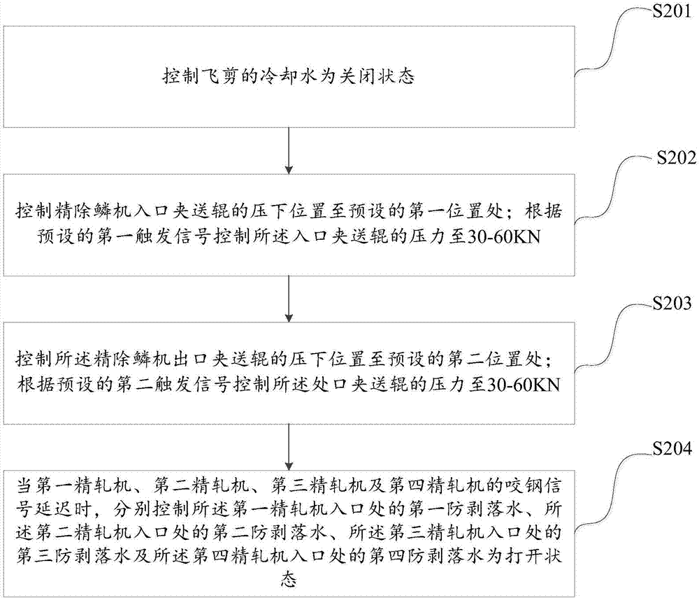
[0055] This embodiment provides a method for controlling the finishing rolling mill, such as figure 2 As shown, the method includes:

[0056] S201, controlling the cooling water of the flying shear to be off.

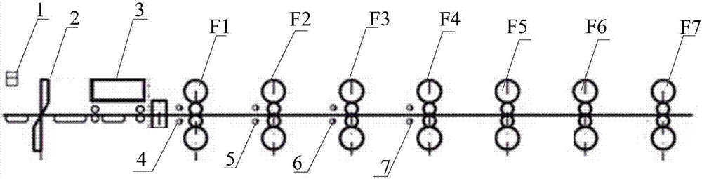
[0057] In this step, when the steel strip normally passes through the hot metal detector 1 at the inlet of the flying shear 2, the cooling water of the flying shear is controlled to be closed, and the position control of the inlet pinch roller and the outlet pinch roller of the fine descaling machine is controlled; It should be noted that the position control is mainly to adjust the gap distance between the inlet pinch roller and the outlet pinch roller of the fine descaling machine.

[0058] S202. Control the pressing position of the inlet pinch roller of the fine descaler to a preset first position; control the pressure of the inlet pinch roller to 30-60KN according to a preset first trigger signal.

[0059] Here, when the position control control signal is receive...

Embodiment 2

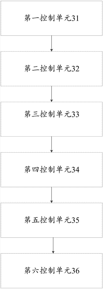
[0073] Corresponding to Embodiment 1, this embodiment also provides a device for controlling the finishing rolling unit, such as image 3 As shown, the device includes: a first control unit 31, a second control unit 32, a third control unit 33, a fourth control unit 34, a fifth control unit 35, and a sixth control unit 36; wherein,

[0074] The first control unit 31 is used to control the cooling water of the hot metal detector and the flying shear to be in a closed state; specifically, when the steel strip normally passes through the hot metal detector 1 at the entrance of the flying shear 2, the first control unit 31 controls the cooling water of the flying shear to be closed, and the second control unit 32 controls the position control of the inlet pinch roller and the outlet pinch roller of the fine descaler; it should be noted that the position control is mainly to adjust the fine descaler The gap distance between the inlet pinch roller and the outlet pinch roller of the ...


PUM


Abstract

The invention provides a method and device for controlling a finishing mill unit. The method comprises the steps of controlling cooling water of a flying shear to be in a turn-off state; controlling the pressing-down position of an inlet pinch roll of a finishing descaling machine to a preset first position; controlling the pressure of the inlet pinch roll to 30-60 KN according to a preset first trigger signal; controlling the pressing-down position of an outlet pinch roll of the finishing descaling machine to a preset second position; controlling the pressure of the outlet pinch roll to 30-60 KN according to a preset second trigger signal; and controlling anti-stripping water at an inlet of a first finishing mill, anti-stripping water at an inlet of a second finishing mill, anti-stripping water at an inlet of a third finishing mill and anti-stripping water at an inlet of a fourth finishing mill to be in a turn-on state correspondingly when steel biting signals of the first finishing mill, the second finishing mill, the third finishing mill and the fourth finishing mill are delayed.

Description

technical field [0001] The invention relates to the technical field of steelmaking, in particular to a method and device for controlling a finishing rolling unit. Background technique [0002] At present, when thick-gauge strips are rolled in the finish rolling area of ​​the production line, the strip tends to warp at the exit of the finishing mill, especially at the exit of F1 and F2 rolling mills. The strip warps not only cause damage to the equipment, but also When the warping head is large, it is easy to hit the entrance of the lower frame and cause a steel pile accident. [0003] Based on this, the present invention provides a method and device for controlling a finishing rolling mill to solve the above-mentioned problems in the prior art. Contents of the invention [0004] Aiming at the problems existing in the prior art, the embodiment of the present invention provides a method and device for controlling the finishing rolling unit, which is used to solve the phenom...

Claims


Application Information

Patent Timeline
Patent Type & Authority Applications(China)
IPC IPC(8): B21B37/00B21B37/72
CPCB21B37/00B21B37/72
Inventor 谭志福陈永平王健张明生崔秋艳李满银赵世民邱绪利窦召科荣彦明
Owner SHOUGANG JINGTANG IRON & STEEL CO LTD
Why Eureka
Try Eureka