Polishing auxiliary device
A technology for auxiliary devices and rotating shafts, which is applied in the direction of grinding drive devices, surface polishing machine tools, grinding/polishing equipment, etc., and can solve problems such as uneven polishing
- Summary
- Abstract
- Description
- Claims
- Application Information
AI Technical Summary
Problems solved by technology
Method used
Image

Examples
Embodiment Construction
[0017] The present invention will be further described below in conjunction with the accompanying drawings.
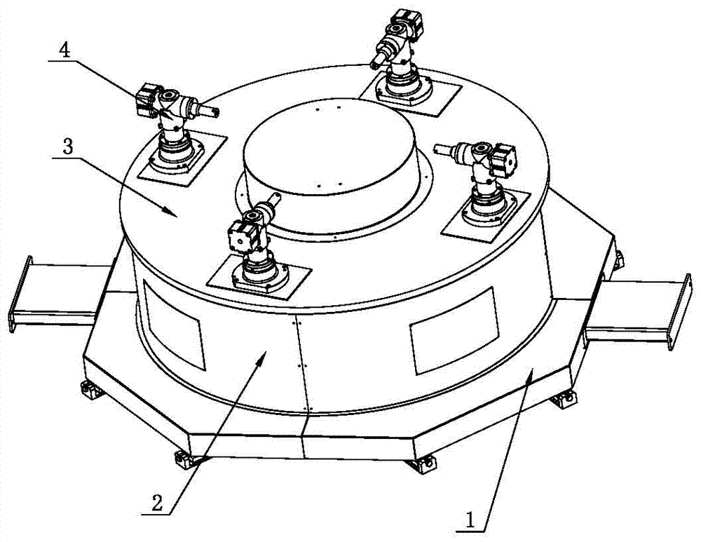
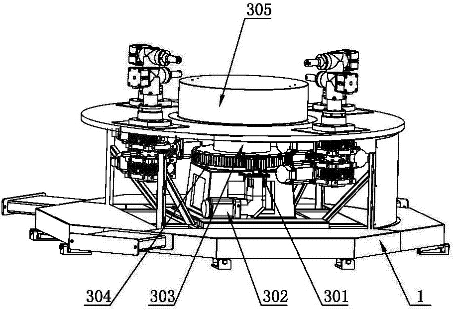
[0018] Such as Figure 1~5 The polishing auxiliary device shown includes a base 1, and a rotatable rotating mechanism 3 is arranged on the base 1. Four clamps 4 for clamping workpieces are arranged on the rotating mechanism 3, and the clamps 4 can rotate by themselves;
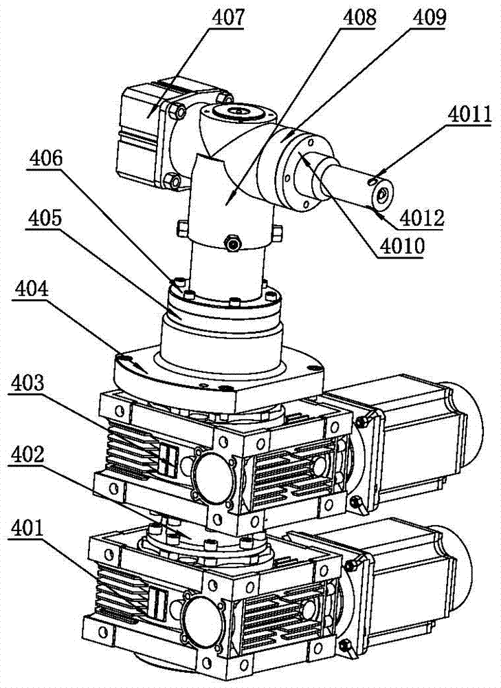
[0019] In order to clamp the workpiece, the fixture 4 includes a cylinder 407, a support swivel base 408 with an accommodating cavity, and a transmission swivel base 409. In the horizontal direction, one end of the support swivel base 408 is connected to the cylinder 407. The housing chamber of 408 performs linear expansion and contraction movement, one end of the transmission swivel seat 409 is in contact with the other end of the support swivel seat 408, the other end of the transmission swivel seat 409 is connected with a clamping seat 4010 having a sliding cavity 4026, and the clamping seat 4010 is...
PUM
 Abstract
Description
Claims
Application Information
 - R&D
- Intellectual Property
- Life Sciences
- Materials
- Tech Scout
- Unparalleled Data Quality
- Higher Quality Content
- 60% Fewer Hallucinations
Browse by: Latest US Patents, China's latest patents, Technical Efficacy Thesaurus, Application Domain, Technology Topic, Popular Technical Reports.
© 2025 PatSnap. All rights reserved.Legal|Privacy policy|Modern Slavery Act Transparency Statement|Sitemap|About US| Contact US: help@patsnap.com