
Blast furnace warm air pipe with high thermal shock resistance

A technology of hot air pipeline and stability, applied in blast furnaces, blast furnace details, blast furnace parts, etc., can solve the problems of poor connection stability of the overall structure, shear force cracks, difficult construction, etc., achieve long service life, eliminate shear Stable and reliable effect of force and structure

Pending Publication Date: 2017-09-01
河南省登封市光大耐火材料有限公司
View PDF3 Cites 4 Cited by
  • Summary
  • Abstract
  • Description
  • Claims
  • Application Information

AI Technical Summary

Problems solved by technology

[0002] Blast furnace ironmaking is currently the most widely used ironmaking method in the world. Usually, each blast furnace is equipped with three to four hot blast stoves. The function of the hot blast stove is to store and provide hot blast for blast furnace smelting. The pipes are connected, and the hot air from the hot blast stove is sent to the blast furnace through the hot blast main pipe, the hot air surrounding pipe and the tuyere device. At present, the method commonly used in the blast furnace hot air pipe is to line the metal shell with fiber cotton and build refractory bricks, and the overall structure is stable. Poor performance, poor sealing, prone to local cracks due to high shear force during thermal expansion, and difficult construction

Method used


Image

  • Blast furnace warm air pipe with high thermal shock resistance
  • Blast furnace warm air pipe with high thermal shock resistance
  • Blast furnace warm air pipe with high thermal shock resistance

Examples


Embodiment Construction

[0015] The following will clearly and completely describe the technical solutions in the embodiments of the present invention with reference to the accompanying drawings in the embodiments of the present invention. Obviously, the described embodiments are only some, not all, embodiments of the present invention. Based on the embodiments of the present invention, all other embodiments obtained by persons of ordinary skill in the art without making creative efforts belong to the protection scope of the present invention.

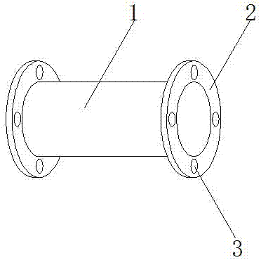
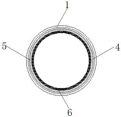
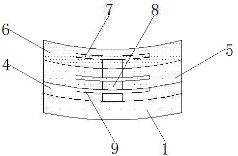
[0016] see Figure 1-4 , an embodiment provided by the present invention: a blast furnace hot blast pipeline with high thermal shock stability, including a steel shell 1, a refractory layer 6, a fixed anchor 7 and a reinforcing rib 10, and connecting flanges are fixed at both ends of the steel shell 1 2, and the connecting flange 2 is provided with a mounting hole 3, the inner wall of the steel shell 1 is provided with a reinforcing rib 10, the inner wall of t...


PUM


Abstract

The invention discloses a blast furnace warm air pipe with high thermal shock resistance. The blast furnace warm air pipe with the high thermal shock resistance comprises a steel shell, a fire resistance layer, a fixing anchor and a reinforced rib plate, connecting flanges are fixed to the two ends of the steel shell, and mounting holes are formed in the connecting flanges; the reinforced rib plate is arranged on the inner wall of the steel shell, a support is fixed to the inner wall of the steel shell, and the fixing anchor and a liner holder are welded to the support; and a thermal insulation layer is arranged in the steel shell, the thermal insulation layer is fixed to the inner wall of the steel shell through the fixing anchor on the support, the liner holder is fixed to a position, between the inner wall of the steel shell and the outer wall of the thermal insulation layer, of the support, and the fire resistance layer is arranged on the inner wall of the thermal insulation layer. The blast furnace warm air pipe with the high thermal shock resistance is convenient to mount, improves the laying efficiency of the blast furnace warm air pipe, is stable in structure, and has excellent thermal shock resistance at a high temperature.

Description

technical field [0001] The invention relates to the technical field of pipeline equipment, in particular to a blast furnace hot blast pipeline with high thermal shock stability. Background technique [0002] Blast furnace ironmaking is currently the most widely used ironmaking method in the world. Usually, each blast furnace is equipped with three to four hot blast stoves. The function of the hot blast stove is to store and provide hot blast for blast furnace smelting. The pipes are connected, and the hot air from the hot blast stove is sent to the blast furnace through the hot blast main pipe, the hot air surrounding pipe and the tuyere device. At present, the method commonly used in the blast furnace hot air pipe is to line the metal shell with fiber cotton and build refractory bricks, and the overall structure is stable. Poor performance, poor sealing, prone to local cracks due to high shear force during thermal expansion, and difficult construction. Contents of the inv...

Claims


Application Information

Patent Timeline
Patent Type & Authority Applications(China)
IPC IPC(8): C21B9/10C21B7/00
CPCC21B7/00C21B9/10
Inventor 陈江伟
Owner 河南省登封市光大耐火材料有限公司
Learn More