Eureka AIR delivers breakthrough ideas for toughest innovation challenges, trusted by R&D personnel around the world.

Underwater rope fisher take-up and pay-off speed control device

A technology of speed control device and overshot, which is applied in the direction of extracting the undisturbed core device, earthwork drilling and mining, etc. It can solve the problems of rope skipping, entanglement to other parts of the subsea drilling rig, and failure of the subsea drilling rig to work normally, so as to achieve simple structure and avoid rope skipping Effect

Active Publication Date: 2017-09-01
HUNAN UNIV OF SCI & TECH
View PDF6 Cites 6 Cited by
  • Summary
  • Abstract
  • Description
  • Claims
  • Application Information

AI Technical Summary

Problems solved by technology

In view of the special working environment of underwater fishing for core pipes, during the process of salvaging core pipes, because the difference between the outer diameter of the overshot and the inner diameter of the drill pipe is very small, the annular flow gap between the overshot and the inner wall of the drill pipe is also very small. Affected by the seawater damping during the lowering of the overshot in the drill pipe and the buoyancy of the overshot itself, when the speed at which the hoist releases the rope is greater than the lowering speed of the overshot, the rope wound on the hoist will skip due to no pre-tension (rope jump out of the hoist), the jumping-out rope is likely to be entangled on other parts of the subsea drilling rig, resulting in the failure of the overshot and the failure of the subsea drilling rig to work normally
During the recovery process of the core pipe carried by the overhauler, when the recovery speed of the overhauler is too fast, the salvage rope may fail and break due to excessive tension

Method used


Image

  • Underwater rope fisher take-up and pay-off speed control device
  • Underwater rope fisher take-up and pay-off speed control device
  • Underwater rope fisher take-up and pay-off speed control device

Examples


Embodiment Construction

[0014] The present invention will be further described below in conjunction with the accompanying drawings and embodiments.

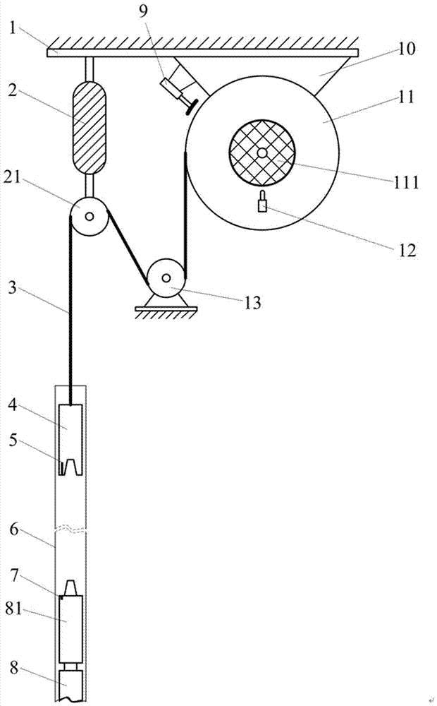
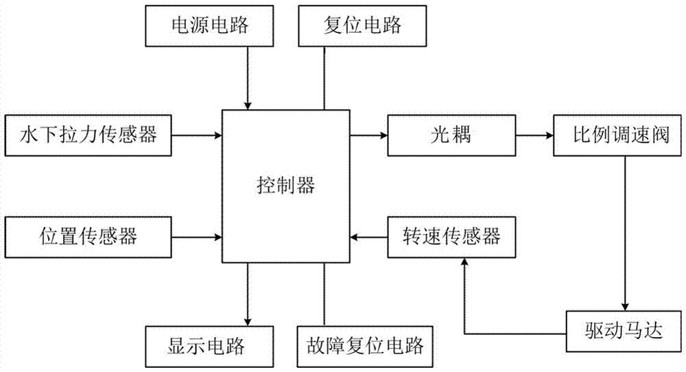
[0015] like figure 1 , figure 2 As shown, a speed control device for retracting and unwinding an underwater rope fisher includes a fisher 4, a rope 3, a hoist 11, an underwater pull force sensor 2, a position sensor 5, a rotational speed sensor 12, a fixed plate 1, a support plate 10, a control device, power supply, display circuit, reset circuit and fault reset circuit; the power supply is connected to the controller to provide working power for the entire control device; the support plate 10 is fixed on the fixed plate 1, and the hoist 11 is fixed on the support plate 10, and the hoist 11 below is provided with fixed pulley 13, and described underwater pulling force sensor 2 is positioned at winch 11 side, and underwater pulling force sensor 2 upper end is fixed on the fixed plate 1, and underwater pulling force sensor 2 lower end is provided with p...


PUM


Abstract

The invention discloses an underwater rope fisher take-up and pay-off speed control device. The underwater rope fisher take-up and pay-off speed control device is characterized by comprising a fisher, a rope, a winch, an underwater tension sensor, a position sensor, a rotating speed sensor and a controller; the underwater tension sensor is fixed to a fixing plate, one end of the rope is wound on the winch, the other end of the rope winds around a fixed pulley and a pulley at the lower end of the underwater tension sensor and is connected with a fisher, the position sensor is fixed to the lower end of the fisher, the rotating speed sensor is installed on a driving motor of the winch, the rotating speed sensor, the underwater tension sensor and the position sensor are connected with the controller, the controller is connected with a proportional speed regulating valve, and the proportional speed regulating valve is located in a hydraulic device of the driving motor. Based on signals collected by the underwater tension sensor, the position sensor and the rotating speed sensor, the rotating speed of the driving motor is controlled to control take-up and pay-off speed of the fisher, the phenomenon that the rope jumps and breaks to fail due to too large tension is effectively avoided.

Description

technical field [0001] The invention relates to the field of marine engineering, in particular to a retractable speed control device for an underwater rope fisher. Background technique [0002] In marine geology research, in order to accurately analyze the distribution of different seabed strata in a designated sea area along the depth direction of the seabed, it is necessary to use seabed drilling equipment to conduct seabed drilling and sampling in the designated sea area, so as to obtain core samples of the seabed strata. In the process of subsea drilling and sampling using subsea drilling equipment such as subsea drilling rigs, after each core tube is cored, it is necessary to use an overshot to salvage the core tubes that have been filled with cores from the bottom of the drill pipe to the core tube of the subsea drilling rig on the storage rack. In view of the special working environment of underwater fishing for core pipes, during the process of salvaging core pipes,...

Claims


Application Information

Patent Timeline
Patent Type & Authority Applications(China)
IPC IPC(8): E21B25/00
CPCE21B25/00Y02A40/81
Inventor 万步炎金永平黄筱军
Owner HUNAN UNIV OF SCI & TECH
Why Eureka
Eureka Blog
Learn More