Crushed thing drying machine

The technology of a dryer and a box body is applied in a field, and can solve the problems of uneven drying degree, reducing the processing quality of the object to be dried, and poor control of air flow.

Inactive Publication Date: 2017-09-01
CY D ENG
View PDF0 Cites 8 Cited by
  • Summary
  • Abstract
  • Description
  • Claims
  • Application Information

AI Technical Summary

Problems solved by technology

[0002] In the structure of the existing dryer, the heat source is realized by the control of such a large and complex process as the central air-conditioning system, and the heat source is only in one area, so a large heat source and a large fan are used to pour hot air into the cavity, not only The flow of wind is not easy to control, and the heat flow is the hottest at the air inlet and the coldest at the end, so that the heat has a gradient change, but the temperature cannot be made uniform; moreover, this type of central air-conditioning system blows the wind into the air at a fixed speed. , it is difficult to accurately control the temperature of each area, so the central centralized air conditioner cannot adjust the temperature of each area according to the demand, resulting in differences in the dryness of the upper and lower surfaces and the interior of the dried o

Method used


Image

  • Crushed thing drying machine
  • Crushed thing drying machine
  • Crushed thing drying machine

Examples


Embodiment Construction

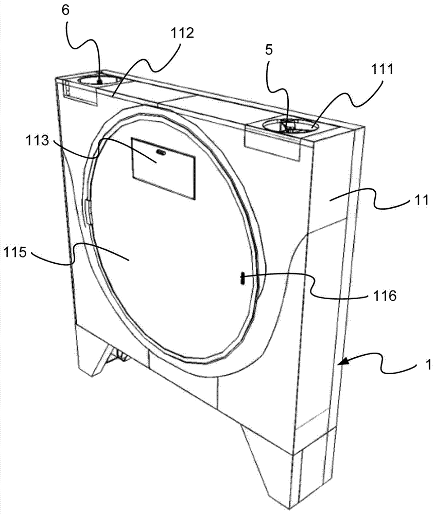
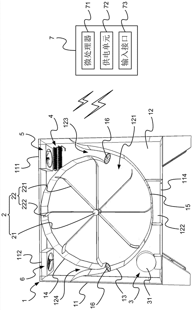
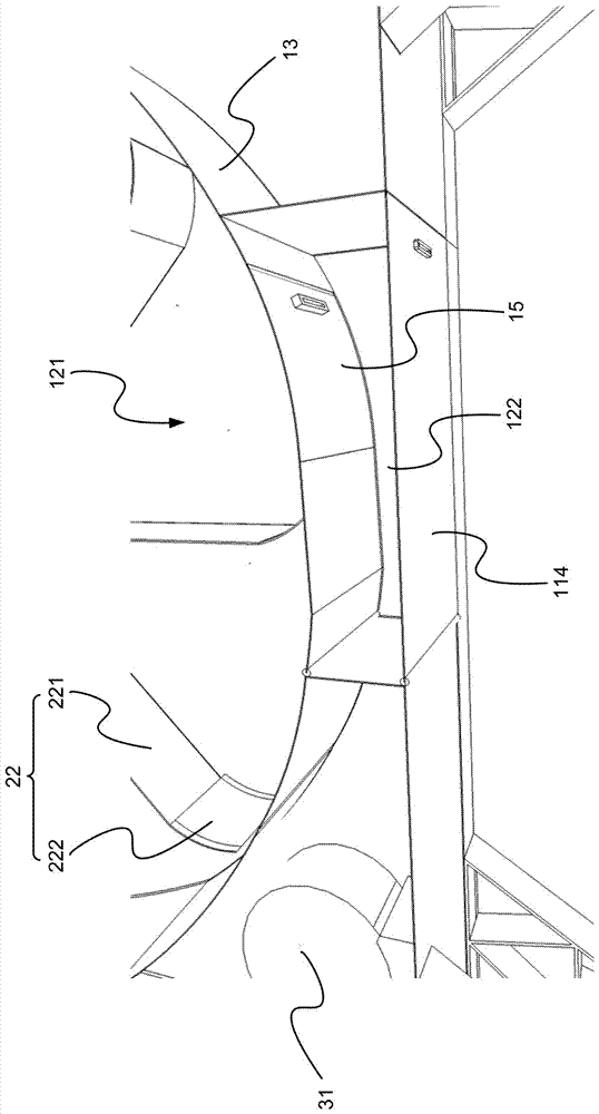
[0061] see Figure 1-Figure 5Shown are the schematic diagram of the appearance of the crumb dryer of the present invention, the schematic diagram of the internal chamber of the crumb dryer of the present invention, the enlarged schematic diagram of a part of the internal chamber of the crumb dryer of the present invention, and the Another partially enlarged schematic diagram of the inner chamber of the inventive crumb dryer, and a schematic diagram of the back of the chamber of the inventive crumb dryer. As shown in the figure: the present invention is a debris dryer, which includes a drying box 1, an agitator 2, a driver 3, several heaters 4 with heat radiation and heat dissipation films, an exhaust fan 5, an exhaust Air fan 6, and controller 7 constitute.

[0062] The upper sides of the shell 11 of the above-mentioned drying box 1 are respectively provided with an air inlet 111 and an air outlet 112, and the front is provided with an inlet door 113, and the bottom is provid...


PUM


Abstract

A debris dryer, comprising a drying box with a chamber, an agitator located in the chamber, a driver, several heaters with heat radiation and cooling films, an exhaust fan and an exhaust fan, and the A controller for the electric connection of the stirrer, the driver, the heater with the heat radiation film, the exhaust fan and the exhaust fan. In this way, this dryer uses an independent and adjustable heating system, so that both the fan speed and the temperature of the heat source can be adjusted according to the needs of the temperature in the mixing chamber, and the fan is used to introduce the airflow, through the heating of the heat dissipation film with heat radiation The device conducts the heat source evenly in the form of fins, and at the same time dries the broken materials evenly through stirring, which has a high drying efficiency. In this way, this work is a distributed heat convection and heat conduction system, the temperature of the heat source, and the speed of the fan and the agitator are all adjustable, and when stirring, it drives the blades to rotate around the shaft instead of driving the entire cavity, so that the internal heat source can be concentrated. Power saving effect of drying and saving energy.

Description

technical field [0001] The present invention relates to a debris dryer, in particular to a heat convection and heat conduction system that combines heating and heat dissipation, especially refers to a highly maneuverable heat source temperature, fan and agitator that can be individually adjusted according to needs Speed, and use the transmission of motor and gear to drive the stirring blade to rotate around the central shaft of the stirring chamber, so that the internal heat source can achieve centralized drying and energy saving. Background technique [0002] In the structure of the existing dryer, the heat source is realized by the control of such a large and complex process as the central air-conditioning system, and the heat source is only in one area, so a large heat source and a large fan are used to pour hot air into the cavity, not only The flow of wind is not easy to control, and the heat flow is the hottest at the air inlet and the coldest at the end, so that the h...

Claims


Application Information

Patent Timeline
IPC IPC(8): F26B11/16F26B25/06F26B25/04F26B25/02F26B21/00F26B25/00F26B25/12
CPCF26B11/16F26B21/001F26B25/00F26B25/02F26B25/04F26B25/06F26B25/12
Inventor 卢鸿智蔡逸伟
Owner CY D ENG
Why Eureka
Try Eureka