Multifunctional rotation device used for carrying out machine vision shooting

A technology of machine vision and rotating devices, which is applied in the direction of optical devices, measuring devices, instruments, etc., can solve the problems of complex control system, narrow detection space, large space occupation, etc., achieve high accuracy of relative angular displacement, reduce calibration difficulty, The effect of taking up little space

Active Publication Date: 2017-09-01
HARBIN UNIV OF SCI & TECH
View PDF12 Cites 20 Cited by
  • Summary
  • Abstract
  • Description
  • Claims
  • Application Information

AI Technical Summary

Problems solved by technology

Binocular or multi-eye vision requires multiple industrial cameras and support frames at the same time. The control system is relatively complex, takes up a lot of space, and the calibration of the coordinate positions between the cameras is complicated and costly. Minimizing the detection space through the research of detection methods has important practical significance for online processing and detection

Method used


Image

  • Multifunctional rotation device used for carrying out machine vision shooting
  • Multifunctional rotation device used for carrying out machine vision shooting

Examples


specific Embodiment approach 1

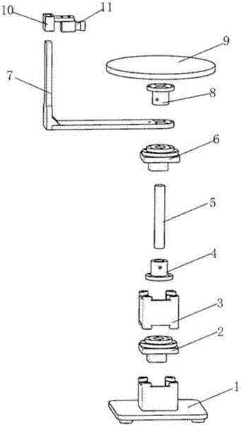
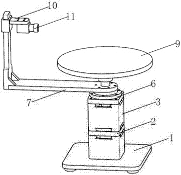
[0024] Embodiment 1: When multiple images are taken from a single viewpoint, the camera 11 is fixed and the object to be photographed is rotated; at this time, the motor II 6 does not work; the camera 11 is fixed on the camera support frame 7 through the camera holder 10, and the Lift and adjust the fixing screw, adjust the camera 11 to a suitable shooting height, and prepare to shoot; the motor I2 drives the carrying tray 9 to rotate through the motor coupling 4 and the tray coupling 8 on the rotating shaft 5, so as to realize the rotation of the object to be photographed, and the object to be photographed Every time a certain angle is rotated, the camera shoots once, and the object to be photographed rotates a circle of 360 degrees, and the camera takes multiple photos.

specific Embodiment approach 2

[0025] Embodiment 2: When multiple images are required to be taken from multiple viewpoints, the object to be photographed is fixed, and the camera 11 is rotated. At this time, the motor I2 does not work; the object to be photographed is placed on the carrier tray 9 and fixed, and the camera 11 is fixed by the camera. The frame 10 is fixed on the camera support frame 7, and the camera 11 is adjusted to a suitable shooting height by adjusting the lifting adjustment fixing screw, and the motor II 6 drives the camera 11 on the camera support frame 7 to rotate. Every time a certain angle is rotated, the camera shoots once, and the camera The support frame 7 rotates 360 degrees in one circle, and the camera takes a plurality of pictures.

specific Embodiment approach 3

[0026] Specific implementation mode three: when it is required to shorten the shooting time and improve the shooting efficiency, the camera and the object to be shot can be reversely rotated at the same time; at this time, the motor I2 and the motor II6 work at the same time; the motor I2 passes through the motor coupling 4 on the rotating shaft 5 and The tray coupling 8 drives the rotation of the object to be photographed on the carrying tray 9 to realize the rotation of the object to be photographed; at the same time, the camera 11 is fixed on the camera support frame 7 through the camera fixing frame 10, and the camera 11 is adjusted by adjusting the lifting adjustment fixing screw. To a suitable shooting height, the motor II 6 drives the camera 11 on the camera support frame 7 to rotate in reverse, and the object to be photographed and the camera 11 are rotated at a certain angle each time, and the camera shoots once, and the object to be photographed and the camera support ...


PUM


Abstract

The invention provides a multifunctional rotation device used for carrying out machine vision shooting. The device comprises a supporting foundation, a motor I, a motor mounting seat, a motor shaft coupling, a rotating shaft, a motor II, a camera supporting rack, a tray shaft coupling, a bearing tray, a camera fixing rack and a camera, wherein the motor I is fixed through the supporting foundation, the motor I is connected with the rotating shaft through the motor shaft coupling to drive the bearing tray to rotate, the bearing tray is connected with the rotating shaft through the tray shaft coupling, the motor I and the motor II are fixedly connected through the motor mounting seat, the motor II is connected with the camera supporting rack, and the camera is connected with the supporting rack through the fixing rack. When the camera is required to rotate 360 DEG to shoot a fixed to-be-shot object, the to-be-shot object is arranged on the bearing tray, the camera supporting rack is driven by the motor II to rotate, and the camera shoots after rotating a certain angle; when the camera is required not to move, the to-be-shot object rotates 360 DEG for shooting, the to-be-shot object on the bearing tray is driven by the motor I through an output rotating shaft to rotate, and the camera shots whenever the to-be-shot object rotates a certain angle. The device is advantaged in that through machine vision multi-angle rotating shooting and scanning, object surface quality detection and three-dimensional surface contour reconstruction are realized.

Description

technical field [0001] The invention relates to a photographing rotating device, in particular to a rotating photographing device used for machine vision to detect the surface quality of an object. Background technique [0002] At present, in the production process of large quantities of industrial products, most of the products still need human eyes to detect the surface quality. Using human eyes to inspect the surface quality of products is inefficient, error-prone, and fatigue-prone, and the labor cost is high, while using machine vision to inspect the surface quality of products can greatly improve efficiency and automation, especially in some working conditions that are not conducive to human entry. Or under extremely harsh conditions, it is of great significance to replace artificial vision with machine vision. [0003] Using machine vision to detect the surface quality of products, to obtain a three-dimensional overall picture of the product, it can be achieved throu...

Claims


Application Information

Patent Timeline
Patent Type & Authority Applications(China)
IPC IPC(8): G01B11/24
CPCG01B11/24
Inventor 张洪鑫王明珠宋现义
Owner HARBIN UNIV OF SCI & TECH
Why Eureka
Try Eureka