Remote displacement measurement device, system and method having clutter inhibition function

A technology for clutter suppression and displacement measurement, which is applied to radio wave measurement systems, measurement devices, and radio wave reflection/re-radiation. It can solve problems such as strong background clutter affecting system accuracy.

Active Publication Date: 2017-09-01
CHENGDU ZERO TECH
View PDF35 Cites 9 Cited by
  • Summary
  • Abstract
  • Description
  • Claims
  • Application Information

AI Technical Summary

Problems solved by technology

[0005] The purpose of the present invention is to provide a remote displacement measurement system with clutter suppression function, to solve the problem that the strong background clutter in the remote high-precision displacement measurement in the prior art will affect the accuracy of the system, the main measurement device and the system in the system of the present invention The slave measurement device adopts a dual-antenna structure with polarization orthogonality, which effectively eliminates the influence of clutter on the measurement accuracy of the system

Method used


Image

  • Remote displacement measurement device, system and method having clutter inhibition function
  • Remote displacement measurement device, system and method having clutter inhibition function
  • Remote displacement measurement device, system and method having clutter inhibition function

Examples


Embodiment 1

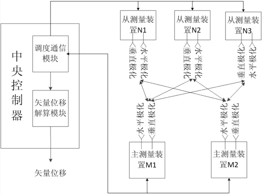
[0060] Such as figure 1 with image 3 As shown, the remote displacement measurement system with clutter suppression function includes a central controller, 2 master measuring devices M1, M2 and 3 slave measuring devices N1, N2, N3. All master measurement devices and slave measurement devices are paired to complete the measurement work under the dispatch of the central controller.

[0061]The central controller includes a scheduling communication module and a vector displacement calculation module; the scheduling communication module is used for: (1) scheduling the pairing of the master measuring device and the slave measuring device so that the master measuring device and the slave measuring device perform pairing measurement; ( 2) control the state of each master measuring device and slave measuring device, and (3) receive the relative displacement of the master measuring device and slave measuring device paired measurement gained from the slave measuring device; The obtain...

Embodiment 2

[0069] On the basis of Embodiment 1, the main measuring device is further improved in this embodiment:

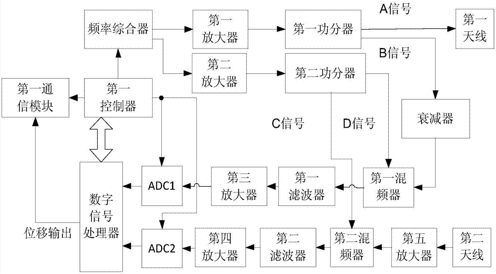
[0070] Such as image 3 As shown, the main measurement device includes a frequency synthesizer, a local oscillator signal processing unit, a transmitting unit, a receiving unit, a reference signal processing unit, a first controller, a digital signal processor and a first communication module, wherein:

[0071] frequency synthesizer for generating a frequency f RF The transmitted signal and frequency are f L local oscillator signal;

[0072] The transmitting unit is used to amplify the transmitting signal generated by the frequency synthesizer and divide it into two channels A and B, the signal of channel A is transmitted through the first antenna, and the signal of channel B is sent to the reference signal processing unit;

[0073] The local oscillator signal processing unit is used to amplify the local oscillator signal generated by the frequency synthesizer and divide...

Embodiment 3

[0088] On the basis of Embodiment 2, further improvements are made to the slave measuring device in this embodiment. When used from the measuring device, it is placed at the measured point and used as an active transponder beacon. Such as Figure 4 As shown, the slave measuring device includes:

[0089] The second communication module is used to communicate with the central controller and obtain control signaling from the central controller;

[0090] The third antenna is used to receive the X-polarized transmission signal transmitted by the first antenna of the main measuring device;

[0091] A program-controlled switch, coupled to the third antenna, is used to control whether the slave measuring device is in a forwarding state or a disconnection state;

[0092] The sixth amplifier, coupled to the program-controlled switch, is used to amplify the X-polarized signal received by the third antenna and output the forwarding signal; when the program-controlled switch controls the ...


PUM


Abstract

The invention discloses a remote displacement measurement device, system and method having a clutter inhibition function. The system comprises a central controller, at least one main measurement device and at least one secondary measurement device, wherein the main measurement device is used for sending an emission signal to the secondary measurement device, receiving a forwarding signal emitted by the secondary measurement device and calculating relative displacement according to the received forwarding signal, the secondary measurement device is used for receiving the emission signal of the main measurement device and emitting the forwarding signal, and the main measurement device and the secondary measurement device both have two sets of polarized orthogonal antennas. When the main measurement device emits the signal, natural landform scattered strong clutter signals and a polarized direction of an emission antenna are consistent, polarized characteristics of a reception antenna and the emission antenna are in polarized orthogonal, so the reception antenna has the quite strong inhibition effect on background clutter, so system precision is improved; during cofrequency transmit-receiving, an acquired transmit-receiving isolation degree can be greater compared with a single antenna and the double polarized antennas, a large measurement distance is acquired through enhancing emission power.

Description

technical field [0001] The invention relates to a remote displacement measurement technology, in particular to a remote displacement measurement device, system and method with clutter suppression function. Background technique [0002] At present, displacement monitoring is one of the most effective early warning methods for landslide geological hazards such as large reservoirs and mountain roads, and remote high-precision displacement measurement is the technical basis for this type of displacement monitoring (Zheng Daqing et al., based on phase measurement Microwave displacement measurement method, "Sensors and Microsystems", 2014 No. 6: 55-57,68). [0003] In the Chinese patent "A Micro-displacement Measurement Technology" (authorized announcement number: CN1271419C), a corner reflector is placed at the measured point, and a strong target echo is obtained through the reflection characteristics of the corner reflector to realize displacement monitoring. However, this tech...

Claims


Application Information

Patent Timeline
Patent Type & Authority Applications(China)
IPC IPC(8): G01S13/87G01S7/02
CPCG01S7/023G01S7/024G01S13/878
Inventor 陈祝明
Owner CHENGDU ZERO TECH
Why Eureka
Try Eureka