A touch display device

A technology for touch display devices and touch electrodes, which is applied in the directions of instruments, calculations, and electrical digital data processing, etc., can solve the problems of weak touch signal strength and poor touch sensitivity at the edge of the display area, and achieve capacitance value enhancement and enhancement. Touch sensitivity, the effect of reducing the difference

Active Publication Date: 2020-06-02
SHANGHAI TIANMA MICRO ELECTRONICS CO LTD
View PDF8 Cites 0 Cited by
  • Summary
  • Abstract
  • Description
  • Claims
  • Application Information

AI Technical Summary

Problems solved by technology

However, due to the different thicknesses of the display panels in the frame area and the display area, the touch signal strength between the touch electrodes formed by the grid-shaped metal traces in the frame area and the touch subject (such as a finger) is higher than that of the grid-shaped metal traces in the display area. The touch signal strength between the touch electrodes composed of wires and the touch body is weak, and the touch electrodes at the edge of the display area are at least partially located in the frame area, so the touch sensitivity at the edge of the display area of ​​the touch display device is poor.

Method used


Image

  • A touch display device
  • A touch display device
  • A touch display device

Examples


Embodiment Construction

[0026] The present invention will be further described in detail below in conjunction with the accompanying drawings and embodiments. It should be understood that the specific embodiments described here are only used to explain the present invention, but not to limit the present invention. In addition, it should be noted that, for the convenience of description, only some structures related to the present invention are shown in the drawings but not all structures.

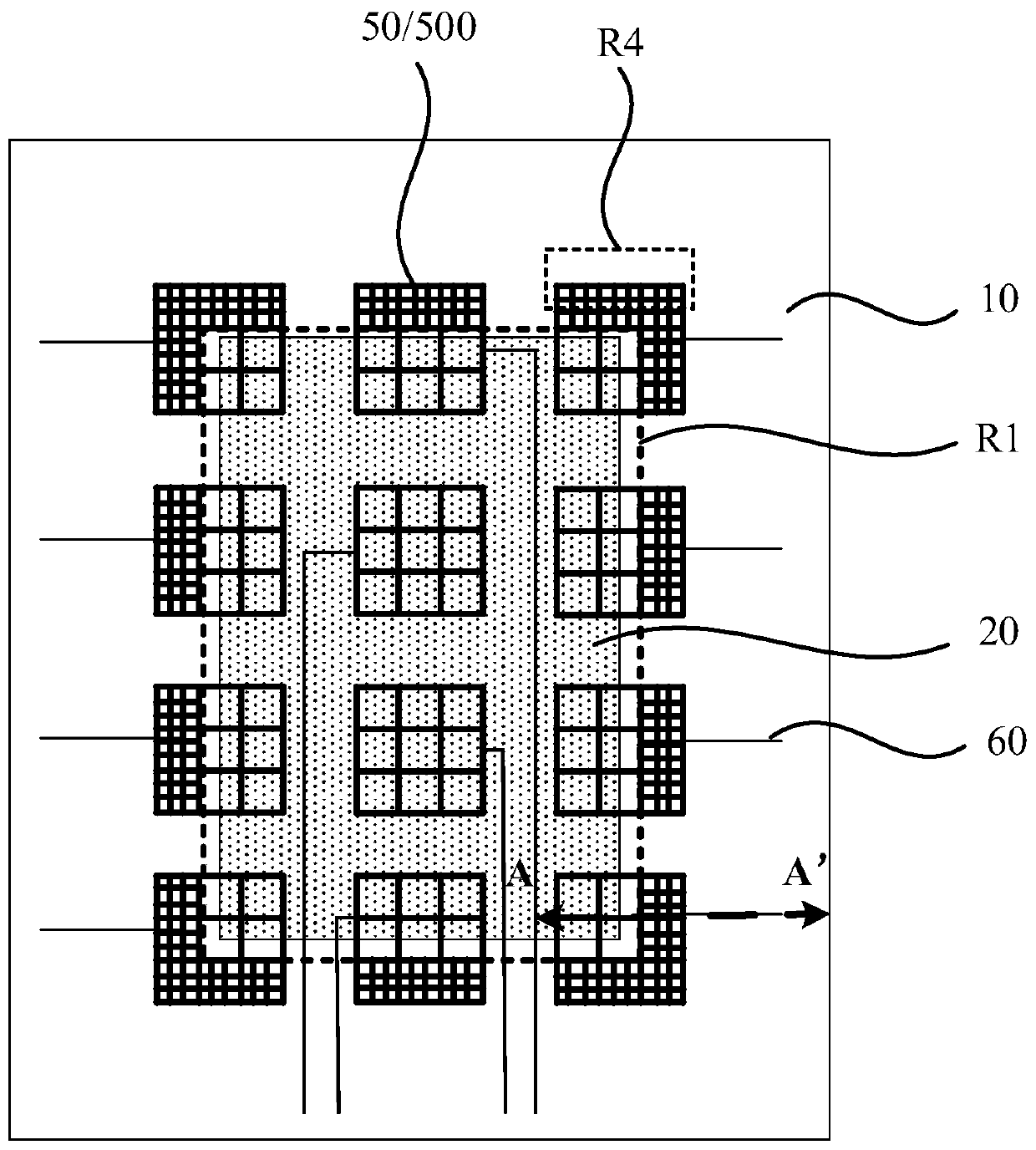
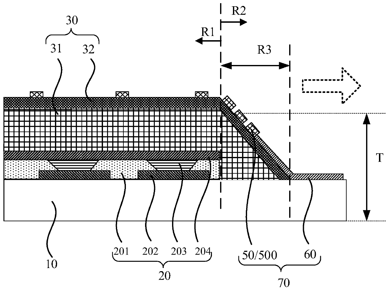
[0027] Figure 1a It is a schematic top view structural diagram of a touch display device provided by an embodiment of the present invention, Figure 1b for along Figure 1a Schematic diagram of the cross-sectional structure in the direction of AA', combined with Figure 1a and Figure 1b As shown, the touch display device has a display area R1 and a frame area R2, and the display area R1 can display information such as graphics and text. The touch display device can be a display panel, or a mobile phone, a tablet...


PUM


Abstract

A touch display apparatus with a display region and a frame region is provided. The touch display apparatus includes a base substrate, a display function layer and a thin film encapsulation layer which are sequentially stacked. The display function layer is located in the display region. A touch electrode layer is arranged at a side, facing away from the base substrate, of the display function layer. The frame region includes a slope region adjacent to the display region. The thickness of the touch display apparatus in the slope region is gradually decreased outward from the display region. The touch electrode layer includes touch electrodes which form a grid of metallic wires. The grid density of the touch electrodes in the slope region is higher than that in the display region.

Description

technical field [0001] The present invention relates to the field of display technology, in particular to a touch display device. Background technique [0002] OLED (Organic Light Emitting Diode, Organic Light Emitting Diode) display is a self-luminous display. Compared with LCD (liquid crystal display, liquid crystal display), OLED display does not require a backlight source, so OLED display is thinner and lighter. In addition, OLED display is also It has the advantages of high brightness, low power consumption, wide viewing angle, high response speed, and wide operating temperature range, and is increasingly used in various high-performance display fields. [0003] Setting the touch electrodes in the OLED as grid-like metal traces can reduce the impedance of the touch electrodes and improve touch sensitivity on the one hand. On the other hand, since the touch electrodes are grid-like metal traces, the grid-like The ductility of the metal traces is good, and the bending re...

Claims


Application Information

Patent Timeline
Patent Type & Authority Patents(China)
IPC IPC(8): G06F3/041G06F3/044
CPCG06F3/0412G06F3/044G06F2203/04111G06F3/04164G06F3/0443G06F3/0445G06F3/0446G06F2203/04112G06F3/047
Inventor 周星耀王丽花姚绮君曾洋
Owner SHANGHAI TIANMA MICRO ELECTRONICS CO LTD
Why Eureka
Try Eureka